


- TOP >
- Gear Knowledge >
- The first step of mechanism design using gears >
- Know about type and strength of gear material
When designing gears, you need to temporarily determine material that is responsible for strength first, as well as various elements of the design such as module.
1. Material selection
To choose a material for general mechanical part, consider the items shown below depending on the application environment. (Table 5-1)
Table 5-1 Items to consider when choosing materials| Metal material | Resin material |
|
|
Choose the cheapest material from those that satisfy function and strength. Materials generally used for gears are :
- Rolled steel for general structure (SS400, SGD400 etc.)
- Cold-rolled steel plate (SPCC etc.)
- Carbon steel for machine structural use (S25C, S45C etc.)
- Alloy steel for machine structure (SCM415, SCM440 etc.)
- Copper alloy (C5191 etc.)
- Steel for special purposes (SUS303 etc.)
- Engineering plastic (MC nylon, polyacetal etc.)
(Note) Material specifications of metals are determined by JIS, and these materials can be obtained only in Japan. When processing overseas, you need to import materials from Japan or choose materials that contain the same elements in proper proportions.
2.Understanding materials used for gears
1. Rolled steel for general structures (SS material)
Steel that assures tensile strength rather than chemical contents. (Table 5-2)
Table 5-2 Component table of SS material (quoted from JIS G 3101)| Steel Designation | Chemical component | Tensile strength N/mm2 | |||
| C | Mn | P | S | ||
| SS330 | - | - | ≤0.050 | ≤0.050 | 330 - 430 |
| SS400 | 400 - 510 | ||||
| SS490 | 490 - 610 | ||||
| SS540 | ≤0.30 | ≤1.60 | ≤0.040 | ≤0.040 | ≥540 |
The content of carbon (C) is not specified for SS330 - SS490. Carbon is responsible for the strength of steel and also influences hardenability.
Therefore, if you choose SS400 material which is frequently used for gears in Japan, you are selecting it for low-strength metal gears which are not hardened.
2. Cold-rolled steel plate (SPC material)
Used for flat plate or curved plate as general sheet-metal part. (Table 5-3)
Table 5-3 Component table of SPC material (quoted from JIS G 3141)| Steel Designation | Chemical component | Tensile strength N/mm2 | |||
| C | Mn | P | S | ||
| SPCC | ≤0.15 | ≤0.60 | ≤0.100 | ≤0.035 | ≥270 |
| SPCD | ≤0.10 | ≤0.50 | ≤0.040 | ||
| SPCE | ≤0.08 | ≤0.45 | ≤0.030 | ||
SPCC is commonly used for gear material as its content of carbon (C) is high and also has versatility. As the thickness is thin, SPCC is used for gears whose strength is lower than SS materials. Their surface cannot be cured by hardening because of the low carbon content, so you need to specify soft nitriding treatment to simply harden their surfaces.
3. Carbon steel for machine structural use (S-C material)
Among various special steels, it is sometimes used after heat treatment and therefore categorized as an alloy steel. Heat-treatment is limited to the surface layer. If the inner part needs to be hard, use an alloy steel for the machine structure.(Table 5-4)
Table 5-4 Component table of S-C material (quoted from JIS G 4051)| Steel Designation | Chemical component | Tensile strength N/mm2 | |||||
| C | Si | Mn | P | S | Normalizing | quenching and tempering | |
| S15C | 0.13-0.18 | 0.15-0.35 | 0.3-0.6 | ≤0.030 | ≤0.035 | ≥370 | - |
| S20C | 0.18-0.23 | ≥400 | - | ||||
| S25C | 0.22-0.28 | ≥440 | - | ||||
| S30C | 0.27-0.33 | 0.6-0.9 | ≥470 | ≥540 | |||
| S35C | 0.32-0.38 | ≥510 | ≥570 | ||||
| S40C | 0.37-0.43 | ≥540 | ≥610 | ||||
| S45C | 0.42-0.48 | ≥570 | ≥690 | ||||
| S50C | 0.47-0.53 | ≥610 | ≥740 | ||||
| S55C | 0.52-0.58 | ≥650 | ≥780 | ||||
The tensile strength of quenching and tempering of carbon (C) is not specified for S15C - S25C because hardness is not improved by heat treatment due to the lower carbon (C) content. Choose this material when you simply want to use metal. If you want to harden the tooth surface of such a low-carbon steel, select these materials after specifying carburizing and quenching that add carbon to the material.
On the other hand, material S30C and below contain more carbon and therefore, are suitable for general hardening. If you want to harden the tooth surface with these materials, specify either quenching & tempering (entire body) or induction hardening (selective portion).
"When you harden, choose either carburizing & quenching or induction hardening depending on carbon content !"

4. Alloy steel for machine structure (SCM material)
Heat treatment is necessary before use. It is commonly called chromium molybdenum steel and has superior hardenability by adding molybdenum. Its strength hardly deteriorates even under high temperature around 500 deg C. (Table 5-5)
Table 5-5 Component table of SCM material (quoted from JIS G 4053)| Steel Designation | Chemical component | Tensile strength N/mm2 | Hardness HBW |
|||||||
| C | Si | Mn | P | S | Ni | Cr | Mo | |||
| SCM415 | 0.13-0.18 | 0.15-0.35 | 0.6-0.9 | ≤0.03 | ≤0.03 | ≤0.25 | 0.6-1.2 | 0.15-0.25 | ≥830 | 235-321 |
| SCM420 | 0.18-0.23 | ≥930 | 262-352 | |||||||
| SCM430 | 0.28-0.33 | 0.15-0.3 | ≥830 | 241-302 | ||||||
| SCM435 | 0.33-0.38 | ≥930 | 269-331 | |||||||
| SCM440 | 0.38-0.43 | ≥980 | 285-352 | |||||||
Specify carburizing & quenching for heat treatment of SCM415 and SCM420 as the carbon (C) content is low (0.15% to 0.20%). As for SCM430 - SCM440, specify quenching & tempering (entire body) or induction hardening (selective portion) as the carbon (C) content is over 0.3%.
5. Cast iron (FC material)
It is characterized by formability of a complicated shape by casting. (Table 5-6)
Table 5-6 Component table of FC material (quoted from JIS G 5501, JIS G 5502)| Steel Designation | Chemical component | Tensile strength N/mm2 | |||||||
| C | Si | Mn | P | S | Mg | Cr | Mo | ||
| FC250 | 3.2-3.5 | 1.7-2.2 | 0.6-0.9 | ≤0.15 | ≤0.10 | - | - | - | ≥270 |
| FCD500 | 3.5-3.6 | 2.5-2.7 | ≤0.4 | ≤0.05 | ≤0.02 | - | ≤0.1 | ≤0.1 | ≥500 |
It has superior wear resistance as the carbon (C) content is much higher than steel. FCD material is suitable for large gears as it attains low noise due to a better vibration damping property.
6. Copper alloy (Cxxx material)
Excellent in corrosion and wear resistance, and used for gears and slide bearings. (Table 5-7)
Table 5-7 Component table of Cxxxx material (quoted from JIS H 5120)| Material Designation | Chemical component | 0.2% offset yield strength N/mm2 | |||||||
| Cu | Sn | P | Pb | Zn | Fe | Sb | Ni | ||
| CAC502A (Phosphor bronze casting) | 87.0-91.0 | 9.0-12.0 | 0.05-0.20 | 0.3 | 0.3 | 0.2 | 0.05 | 1.0 | ≥120 |
Used for a general gear, but especially suitable for a worm wheel which generates sliding friction.
7. Steel for special purposes (SUS material)
Stainless steel should be used if corrosion resistance is required. Stainless steel contains ≤ 1.2% carbon (C) and ≥10.5% chromium (Cr). SUS303 and SUS304 is austenitic stainless steel with excellent corrosion resistance, while SUS440C is martensitic stainless steel with high strength. (Table 5-8)
Table 5-8 Component table of SUS material (quoted from JIS G 4305)| Steel Designation | Chemical component | Offset yield strength N/mm2 | Tensile strength N/mm2 | ||||||
| Cu | Si | Mn | P | S | Ni | Cr | |||
| SUS303 | ≤0.15 | ≤1.0 | ≤2.0 | ≤0.20 | ≥0.15 | 8.0-10.0 | 17.0-19.0 | ≥205 | ≥520 |
| SUS304 | ≤0.08 | ≤1.0 | ≤2.0 | ≤0.045 | ≤0.03 | 8.0-10.5 | 16.0-18.0 | ≥205 | ≥520 |
| SUS440C | 0.95-1.20 | ≤1.0 | ≤1.0 | ≤0.04 | ≤0.03 | ≤0.75 | 16.0-18.0 | - | - |
SUS303 has better machinability than SUS304 because of a high sulfur (S) content.
8. Engineering plastic
Resin material is used for gears for cutting cost, reducing weight, and rust-proofing.
Nylon and POM (polyacetal) with self-lubricity are commonly used as materials.
As for nylon-based materials, MC901 (machining) and M90 (injection molding) are used.
As for polyacetals, Duracon® (product name of Polyplastics) is generally used.
On the other hand, ABS, PC (polycarbonate) and acryl which are commonly used for resin molding products like covers are unsuitable for machine element parts like gears because they become fragile due to solvent cracking (chemical cracking) if oil such as grease adheres.
You need to design peripheral parts carefully to prevent grease and oil on rotating resin gears from scattering and adhering on ABS, PC, or acryl parts which may result in cracking.
3. Combination and hardness of gear material
Material of a pair of gears can be roughly determined by the size of the load. (Table 5-9)
Table 5-9 Combination of gear materials| Load (PV value) |
Drive gear | Driven gear | Remarks |
| Light load | resin, copper alloy, steel (no heat treatment) | resin | Heat hardly escapes when resin gears mesh at high speed, while cooling effect is obtained if combined with metal gear. |
| Medium load | steel | copper alloy, steel | Basically, steel needs heat treatment. |
| Heavy load | steel (with heat treatment) | steel |
Hardness needs to be specified on the drawing when heat-treating steel gears. Refer to catalogs of gear manufacturers for indication of hardness. (Table 5-10)
Table 5-10 Indication of gear hardness (reference specs in catalogs)| Material | Heat treatment | Hardness indication |
| S45C (carbon steel for machine structural use) | without heat treatment | HB194 and under |
| thermal refining (quenching & tempering) |
HB225-260 | |
| induction hardening | HRC45-55 | |
| SCM440 (chromium-molybdenum steel) | thermal refining (quenching & tempering) |
HB225-260 |
| induction hardening | HRC45-60 | |
| SCM415(chromium-molybdenum steel) | carburizing & quenching | HRC55-60 |
* HB (Brinell hardness): measured by pressing hard metal ball on relatively soft material
* HRC (Rockwell hardness): measured by pressing diamond indenter on material harder than HB
4. Strength of gears
Strength calculation of gears has two types: "bending strength" and "tooth surface strength". You need to calculate both to check if strength is assured.
1. Tooth bending strength
Tooth breaks from dedendum when large force is applied.
Tooth bending strength must be checked to prevent breakage. (Figure 5-1)
You can take the following measures to enhance tooth bending strength:
- Enlarge module
- Enlarge tooth width
- Use material with large tensile strength
- Increase pressure angle
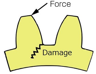
Figure 5-1 Tooth bending stress
2. Tooth surface strength
Large surface pressure applied to tooth surface induces peeling and abrasion.
Tooth surface strength must be checked to prevent surface damage. (Figure 5-2)
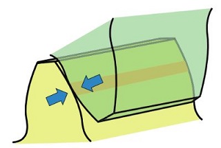
Figure 5-2 Tooth contact stress
You can take the following measures to enhance strength:
- Harden tooth surface by heat-treating
- Enlarge pitch circle diameter of tooth to reduce force toward the circumferential direction
- Increase tooth width
- Reduce surface roughness by polishing tooth surface
We discussed types and strength of materials to be chosen when designing gears.
" Thank you ! "

This concludes "The first step of mechanism design using gears" (Total of 5 Chapters). Thank you for reading !
*Illustration: KAOSUN
相关链接 - 了解齿轮材料的种类和强度
DISCLAIMER
The purpose of writing this article was to educate the readers with the elementary level of gear technology.
We hope that the actual design and manufacturing of gears and machinery utilizing gears are done with sufficient technical and specialized considerations under the user's full responsibility.
We disavow any liability and will not compensate for any direct or indirect damages caused by the gears designed by the users who read this article.