


- TOP >
- Gear Knowledge >
- The first step of mechanism design using gears >
- Know about rotational directions and numbers of rotation of gears
1. Gear functions
Here is the list of gear functions for mechanism designs. (Table 2-1)
Table 2-1 Gear functions| Characteristic functions of gears | Explanation |
| Change direction of rotating shaft | (already explained) |
| Convert rotary motion to linear motion | (already explained) |
| Change rotational direction (clockwise / counterclockwise) | See this chapter |
| Change the number of rotations (speed up / down) | See this chapter |
| Change turning force (increase / decrease torque) |
You can change the directions and the number of rotations of the input and output shafts by meshing several gears. Let me explain this with commonly used cylindrical gears.
2. Definition of rotational direction
Generally, a motor is used as the power source when using gears in designing mechanisms of mechatronics products. Rotational direction of the motor is defined by the rotation of the shaft as seen from the side the motor shaft projects out. (Figure 2-1)
By the way, the spin to the right is commonly abbreviated as CW (clockwise) while the spin to the left as CCW (counterclockwise).
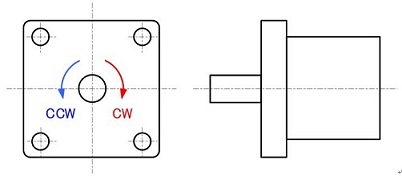
Figure 2-1: Definition of the rotational direction of the motor
Mechanical design engineers need to convey information about a motor’s rotational direction to electric design engineers and software design engineers.
Unlike motors, the rotational direction of gears can be defined differently depending on the viewing direction. Therefore, viewing directions need to be consistent when showing mechanism movement with pictures (Figure 2-2).
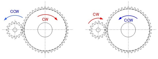
Figure 2-2: Definition of the rotational direction of gears as seen from a predetermined viewing direction

"CW and CCW are frequently appearing words in mechatronics product development and, therefore, important for you to remember !"
3. Speed ratio (speed increasing / decreasing ratio)
The aim of mechanism design with gears is to acquire the necessary rotational number by combining several gears.
The rotational speed of the output shaft is decreased, increased or made the same compared to that of the input shaft depending on the purpose of the application.
The torque becomes smaller when increasing speed and becomes larger when decreasing. (This point will be explained in the next chapter.) Therefore, the speed of a small output power of a motor is decreased with gears to produce larger torque in most cases. Many geared motors are used in automotive parts, home appliances, and motors of industrial machines.
Geared motor is an electrical part consisting of a small motor and a gear box to produce larger torque rather than to lower the motor’s rotational speed. (Figure 2-3)
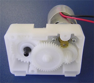
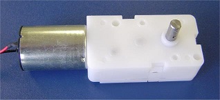
Figure 2-3 : Mechanism of geared motor
4. Speed ratio calculation of a single stage gear train
Rotational number of gears depend completely on the number of teeth of meshing gears and is transmitted as calculated.
A gear train that meshes in the same plane is called a “single stage gear” and the following formulas apply: (Figure 2-4)
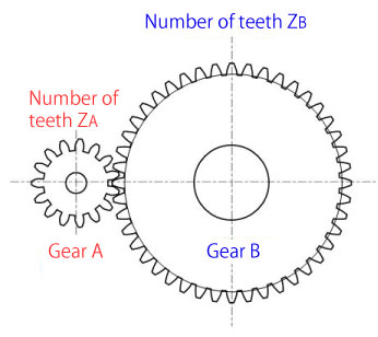
When gear A rotates by rotational number NA, gear B’s rotational number NB slows down to:
NB=(ZA/ZB)× NA
When gear B rotates by rotational number NB, gear A’s rotational number NA increases speed.
NA=(ZB/ZA)× NB
Figure 2-4: Formulas of a single stage gear’s speed ratio
Exercise problem for speed ratios (1)
Calculate rotational number and rotational direction of the driven gear (gear A).
Symbol in Figure 2-5 represents the drive gear.
* rpm: revolution per minutes : number of rotation in one minute. By the way, revolution per second is “rps”.
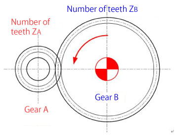
[Condition]
Number of teeth: ZA=20, ZB=40
Rotational number of the drive gear: NB=125rpm
Rotational direction of the drive gear: CCW
[Answer]
Rotational number of gear A
NA=(ZB/ZA)× NB= (40/20)× 125 = 250rpm
Rotational direction of gear A: CW
Figure 2-5: Exercise problem for speed ratios of a single stage gear (1)
Exercise problem for speed ratios (2)
Calculate rotational number and rotational direction of the driven gear (gear B).
Symbolin Figure 2-6 represents the drive gear.
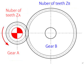
[Condition]
Number of teeth: ZA=17, ZB=51
Rotational number of the drive gear: NA=1800rpm
Rotational direction of the drive gear: CCW
[Answer]
Rotational number of gear B
NB=(ZA/ZB)× NA= (17/51)× 1800 = 600rpm
Rotational direction of gear B: CW
Figure 2-6: Exercise problem for speed ratios of a single stage gear (2)
Exercise problem for speed ratios (3)
Calculate rotational number and rotational direction of the driven gear (gear C).
Symbolin Figure 2-7 represents the drive gear.
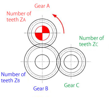
[Condition]
Number of teeth: ZA=20, ZB=30, ZC=20
Rotational number of the drive gear: NA=90rpm
Rotational direction of the drive gear: CCW
[Answer]
Rotational number of gear B:
NB=(ZA/ZB)× NA= (20/30)× 90 ≈ 60rpm
Rotational direction of gear B: CW
NC=(ZB/ZC)× NB= (30/20)× 60 = 90rpm
Rotational direction of gear C: CCW
Figure 2-7: Exercise problem for speed ratio of a single stage gear (3)
These calculations become increasingly cumbersome as the number of gears increases. (Figure 2-8)
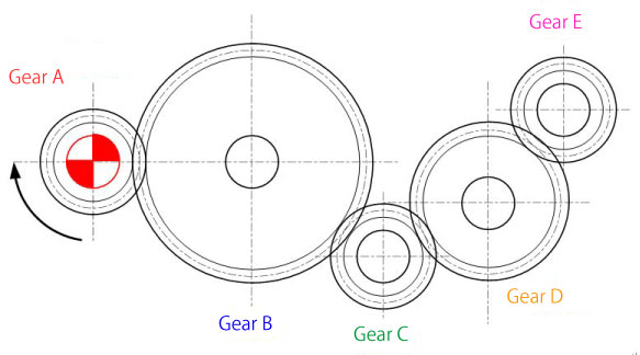
Figure 2-8: Speed ratio calculation of a single stage gear
No problem!
If several gears mesh in a single stage gear, the rotational number is determined by the numbers of teeth of the input and the output gears regardless of the number of gears and teeth in the middle.
Therefore, the rotational number of gear E is calculated as follows:
NE=(ZA/ZE)× NA

"Calculation for a single stage gear is easy even if the number of meshing gears increases !"
5. Speed ratio calculation of a multistage gear train
A gear train that meshes in more than one plane is called a “multistage gear”. (Figure 2-9)
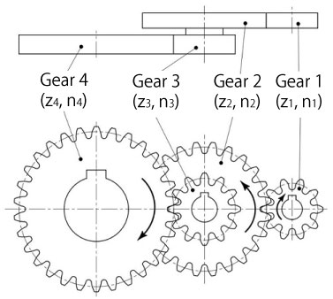
Figure 2-9: Example of a multistage gear train (two-stage)
In this case, you need to calculate the speed ratio for each meshing pair.
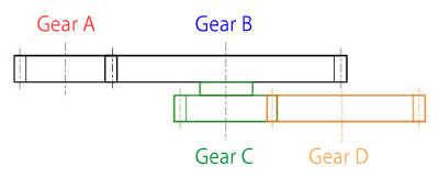
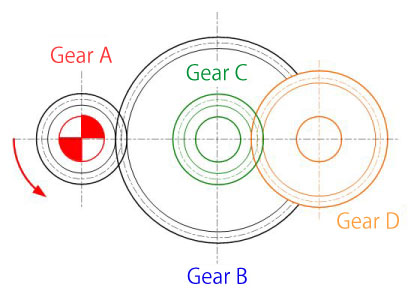
Exercise problem for speed ratios (4)
Calculate rotational number and rotational direction of the driven gear (gear D).
Symbolin Figure 2-10 represents the drive gear.
[Condition]
Number of teeth: ZA=20, ZB=40, ZC=20, ZD=30
Rotational number of drive gear: NA=120rpm
Rotational direction of drive gear: CCW
[Answer]
Rotational number of gear B:
NB=(ZA/ZB)× NA= (20/40)× 120 = 60rpm
Rotational direction of gear B: CW
NC= NB= 60rpm (on the same shaft)
Rotational direction of gear C: CW
ND=(ZC/ZD)× NC= (20/30)× 60 ≈ 40rpm
Rotational direction of gear D: CCW
Figure 2-10: Speed ratio calculation of a multistage gear train
As the speed decrease / increase ratio becomes larger, one gear needs to be larger and there won’t be much space if you use a single stage gear. Therefore, it becomes necessary to use multistage gears to utilize space effectively.
We discussed that the gear rotational number is calculated from the number of teeth in this section.
Next we will explain torque transmission, one of the most crucial elements in designing mechanisms with gears. (To be continued...)
相关链接 - 了解齿轮的旋转方向和旋转数
DISCLAIMER
The purpose of writing this article was to educate the readers with the elementary level of gear technology.
We hope that the actual design and manufacturing of gears and machinery utilizing gears are done with sufficient technical and specialized considerations under the user's full responsibility.
We disavow any liability and will not compensate for any direct or indirect damages caused by the gears designed by the users who read this article.