


- TOP >
- Gear Knowledge >
- The first step of mechanism design using gears >
- Know about parameters that determine gear shapes
Understanding various technical terms is essential in designing gears.
In this chapter, we explain the terms and their meanings of gear parameters.
1. Gear shapes
In general, tooth profiles with involute curves are used for shaping gears. (Figure 4-1)
“Involute curve” is the curve drawn by the end of the thread which is being unwound from a cylinder under tension.
The characteristics of the involute curves are:
- Meshes properly even when the distance between shafts has a slight error
- Easy to form correct tooth profile
- Rotates smoothly since the gears mesh while rolling on a curve

Figure 4-1 Involute curve
2. Types of design parameters necessary for gear design
Parameters needed for gear design are shown below. (Figure 4-2)
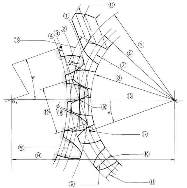
1. Tip circle
2. Reference circle
3. Base circle
4. Root circle
5. Tip diameter
6. Reference diameter
7. Base diameter
8. Root diameter
9. Addendum
10. Dedendum
11. Tooth depth
12. Facewidth
13. Center line
14. Center distance
15. Reference pitch
16. Pitch point
17. Interference point
18. Backlash
19. Length of path of contact
(line of action)
3. Basic parameters necessary for gear design
1. Module
The module is the size of a tooth in mm.
As the module cannot be measured directly with a caliper or a scale, novice designers may be perplexed by the module at first when designing a gear.
The module is the numeric value obtained by dividing the pitch diameter by the number of teeth and is expressed by the formula below :
m = d / z
m: module, d: pitch diameter, z: number of teeth
The value of the module is determined by the standard numbers.
The standard number is the numeric value to be commonly used when manufacturing industrial products.
According to JIS B 1701:2017, the standard values of a module for involute gears are set as shown below. Use of modules on I series are preferred. (Table 4-1)
| I series | 0.1 0.2 0.3 0.4 0.5 0.6 0.8 1 1.25 1.5 2 2.5 3 4 5 6 8 10 12 16 20 25 32 40 50 |
| II series | 0.15 0.25 0.35 0.45 0.55 0.7 0.75 0.9 1.125 1.375 1.75 2.25 2.75 3.5 4.5 5.5 (6.5) 7 9 11 14 18 22 28 36 45 |
The module is changed depending on PV values.
The PV value is obtained by multiplying the load pressure P by the slip speed V.
Therefore, the module needs to be set larger as the load applied to the gear and its rotational speed increases. On the other hand, the module can be set smaller as the load applied to the gear and its rotational speed decreases.
It must be very difficult to choose the size of the module when designing gears for the first time. Designers must proceed with the design work by adjusting various parameter values including module as well as examining size and strength.
There are two ways to temporarily determine the module value.
1. Determine the module value temporarily empirically
Understanding modules of gears used in various products helps to determine the module value.
EX)
Wrist watches ... approx. 0.05 - 0.2
Printers and copiers in office ... approx. 0.6 - 1.0
Racks and pinions for car steering ... approx. 1.75 - 2.5
Transmission for car ... approx. 1.5 - 3.0
2. Determine the module value temporarily from a catalog of commercial standard gears
Catalogs have allowable torque values by material or module. You can refer to the values to determine the module temporarily.
2. Pressure angle
The pressure angle is the angle at which the tooth inclines against the normal line to the pitch line. (Figure 4-3)
Generally, a pressure angle of 20° is used. However, pressure angles of 14.5° or 17.5° are also sometimes used. The larger the pressure angle is, the dedendum becomes wider and strength improves.
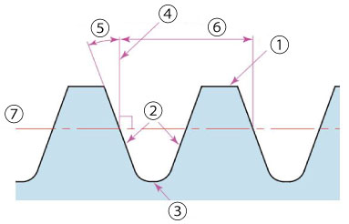
1. Addendum
2. Tooth surface
3. Dedendum
4. Normal line to the pitch line
5. Pressure angle
6. Pitch
7. Pitch line
3. Number of teeth
You need to determine the number of teeth of a pair of meshing gears to calculate the speed ratio as explained in the second article. Be careful about minimum number of teeth (except for worm).
The number of teeth of the pinion needs to be reduced as much as possible to enlarge speed reduction or increase ratio. However, the tip of the rack type tool may overlap with the dedendum and the tip may gauge the dedendum if the number of teeth is below a certain value. (Figure 4-4)
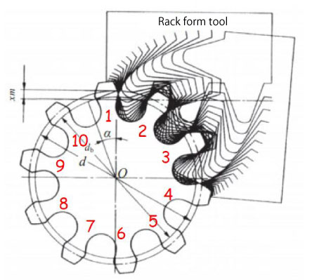
"Dedendum looks fragile and could break when the number of teeth is 10..."

This is called “interference of tooth” and the tooth tapered toward the dedendum is called “undercut”. (Figure 4-5)
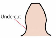
Figure 4-5 Undercut
The limit of the number of teeth to prevent the undercut is given by the following formula. When pressure angle α = 20°, the limiting number is 17.
z = 2 / sin2α
However, it does not mean the gear with undercut is useless. Generally, the practical minimum number of teeth is 14.
To prevent undercut, you can use “shift” (changing distance between the gear cutting tool and the gear).
Due to the limitation of the minimum number of teeth, the diameter of the pinion cannot be extremely small. Therefore, if you want to increase the reduction ratio, the meshing gear becomes large, and you need to take into account the space required in your design.
4. Twist direction
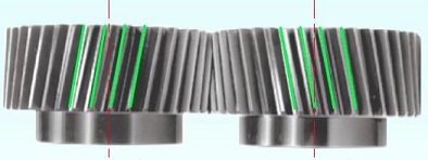
Gears with right-hand teeth have the teeth inclined to the right relative to the gear shaft when you hold the shaft upright, while gears with left-hand teeth have the teeth inclined to the left. As for racks and worms, the gears with right-hand teeth have the teeth rise to the right when you hold the shaft upright, while the gears with left-hand teeth rise to the left.
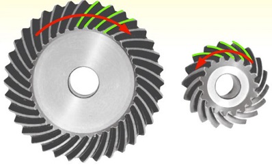
A pair of helical gears or spiral bevel gears needs to have the same module and pressure angle, but in addition, you need to pay attention to the twist direction.
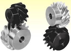
As for teeth of helical gears, spiral bevel gears and racks, the twist direction of gears should be opposite to each other to mesh. (Figure 4-6)
Two helical gears which have the teeth incline to the same direction never mesh, so you need to prepare two helical gears whose twist directions are opposite.
Right-hand teeth / Left-hand teeth
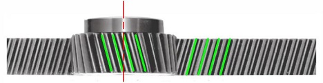
Pinion: left-hand teeth, Rack: right-hand teeth
Pinion: right-hand teeth, Rack: left-hand teeth
Right-hand teeth / Left-hand teeth
Figure 4-6 Gears whose twist directions are the opposite
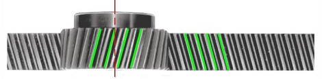
On the other hand, twist directions of gear teeth of screw gears or worm gears used for skew shafts need to be the same to mesh. (Figure 4-7)
Right-hand teeth / Left-hand teeth
a) Screw gear
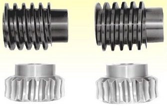
Right-hand teeth / Left-hand teeth
b) Worm gear
Figure 4-7 Gears whose twist directions are the same
"Meshing twist directions vary according to the gear types !"

5. Torsion angle
The tooth is inclined relative to the axis of the cylinder.
This inclination amount is called "torsion angle". (Figure 4-8)
The screw gears shown in Figure 4-7 have the torsion angle of 45°.
You can decide the torsion angle of meshing two gears freely, but note that the thrust direction (axial direction) component becomes larger as the torsion angle increases, and the machine efficiency deteriorates as a result. Below 25° is desirable for general helical gears to avoid too much thrust.
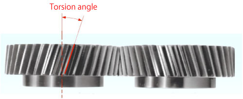
Figure 4-8 Torsion angle of helical gear
We discussed parameters necessary for gear design and their meanings.
Next we will explain types of gear material.
(To be continued...)
*Illustration: KAOSUN
相关链接 - 了解决定齿轮形状的要素
DISCLAIMER
The purpose of writing this article was to educate the readers with the elementary level of gear technology.
We hope that the actual design and manufacturing of gears and machinery utilizing gears are done with sufficient technical and specialized considerations under the user's full responsibility.
We disavow any liability and will not compensate for any direct or indirect damages caused by the gears designed by the users who read this article.