


- TOP >
- Gear Knowledge >
- The first step of mechanism design using gears >
- Know about gear types and relations between the two shafts
Introduction
Recently, products with new and innovative structures are rarely developed. Rather, in most cases, only specification and design changes of existing models are done.
Therefore, it is desired of design engineers to acquire the skills to change some structures of existing models or parts to develop new products.
Design engineers should take responsibility in case of failure due to a major change of structure or part design because of arbitrary judgements of the engineer. Such are the current situations that most engineers just copy and paste using CAD without learning about principles of structure and mechanisms.
Incidentary, radio-cassette players and CD players, which were widely favored for a hobby or automobile use, had a reliable structure because of links, gears, and springs tightly arranged in a narrow space. Nowadays, we can play music only by inserting a USB or with wireless communication, and therefore all the machine design engineers need to design is a chassis containing non-moving parts to place an electronic substrate.
Such changes in our era also decreased machine design engineers’ opportunities to be exposed to mechanism design which eventually led to the lack of creativity to develop new structures and mechanisms.
Now, how should machine design engineers face mechanism design tasks when altering existing models and functions are weakened ?
In this chapter, basic knowledge of gears is explained before proceeding to invent mechanisms with gears.
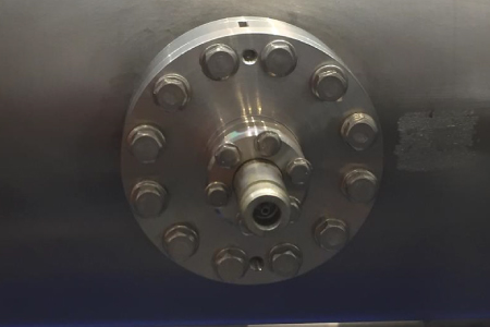
1. Machine elements
Machine elements are the smallest units of functional parts (e.g. bolt, nut, gear, key, etc.) among components constituting a machine as shown in the table below (table 1-1).
Table 1-1 Machine elements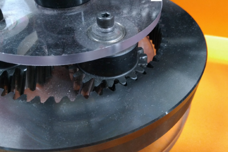
Gear
Function:
Transmits continuous rotary motion
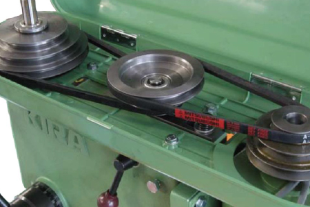
Belt & Pulley / Chain & Sprocket
Function:
Transmits continuous rotary motion
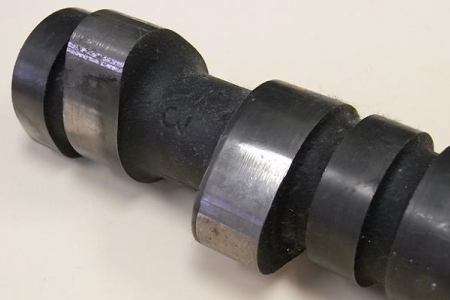
Cam
Function:
Converts rotary motion to non-continuous linear motion
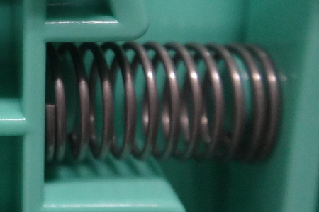
Spring
Function:
Stores load, absorbs impact
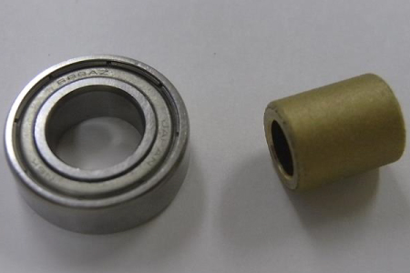
Roller Bearing / Sliding Bearing
Function:
Supports rotary shaft
Screw / Bolt / Nut / Washer / Feed Screw
Function:
Secures parts / Converts rotary motion to linear motion
Key / Pin / Retaining Ring
Function:
Secures hub on the shaft so as not to slip in the rotational direction / Prevents part from slipping off the shaft in the axial direction
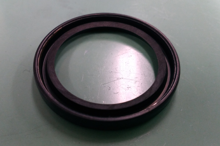
O ring / Oil seal / Dust seal / Packing
Function:
Seals fluid or gas / Prevents foreign matter from getting inside
2.Types of drive transmission elements
Among machine elements, drive transmission elements are categorized into the following groups. (Table 1-2)
Table 1-2 Types of drive transmission elements| Drive transmission | Rigid contact transmission | Mesh transmission | Gears, etc. |
| Friction transmission | Friction rollers, etc. | ||
| Non-rigid contact transmission | Mesh transmission | Timing belts and chains | |
| Friction transmission | Flat belts, etc. | ||
| Non-contact transmission | Magnetic power transmission | Magnet gears, etc. |
Among these drive transmission elements, the mesh transmission gears are used for general mechanisms.
Gears are defined as “machine elements to transmit rotary motion by successively meshing the concave surface on one shaft with the convex surface (teeth) on the other shaft".
3.Gear functions
Here is the list of gear functions for mechanism designs. (Table 1-3)
Table 1-3 Gear functions| Characteristic functions of gears | Explanation |
| Change direction of rotating shaft | See this chapter |
| Convert rotary motion to linear motion | See this chapter |
| Change rotational direction (clockwise / counterclockwise) | |
| Change the number of rotations (speed up / down) | |
| Change turning force (increase / decrease torque) |
Among various characteristics like shape, purpose, material, a designer first needs to review the layout of the two shafts on which gears are mounted.
The gear type determines the direction of the two shafts.
The layout of the gear shaft can be categorized into three as shown below. (Table 1-4)
Table 1-4 Gears by shaft layout
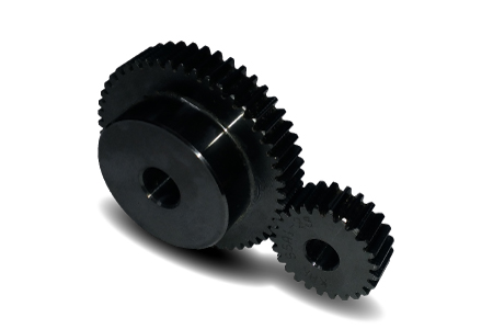
Gears for parallel shafts
Spur gears / Helical gears / Double helical gears / Internal gears / Gear rack (for linear motion)
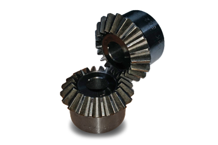
Gears for intersecting shafts
Straight bevel gears / Spiral bevel gears
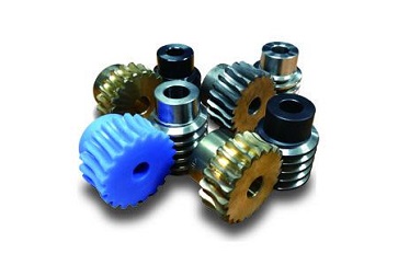
Gears for skewed shafts
Cylindrical worm gears / Screw gears / Hypoid gears
Let’s look at the types and characteristics of gears for the parallel shafts. (Table 1-5)
Table 1-5 Types and characteristics of gears for the parallel shafts
Spur Gears
Cylindrical gears whose tooth traces are straight and parallel to the shaft. Have better machine efficiency thanks to teeth parallel to the shaft, but are inferior in strength and quietness when meshing due to the smaller contact ratio compared to helical gears.
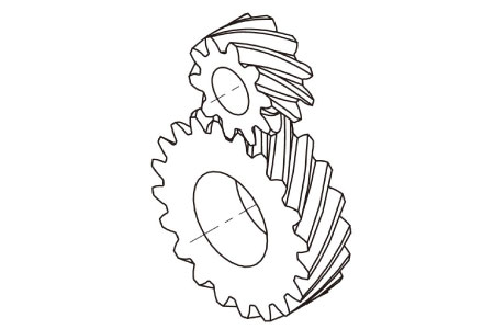
Helical Gears
Cylindrical gears whose tooth traces are diagonal to the shaft. The machine efficiency is less than spur gears due to thrust forces generated by diagonal teeth. However, they are better in strength and quietness when meshing due to the larger contact ratio than spur gears.
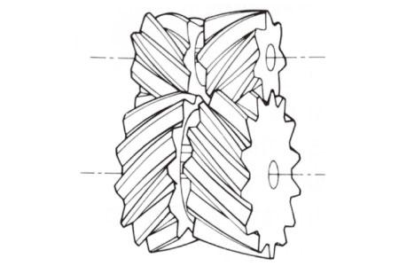
Double Helical Gears
Combined two helical gears whose twist directions are opposite. Used to reduce thrust forces in the axial direction because the gears balance thrust forces generated by meshing.
Internal Gears
Gears having teeth inside cylinder. Tooth trace is either parallel to the shaft and straight or diagonal to the shaft. Can be utilized to make efficient use of space.
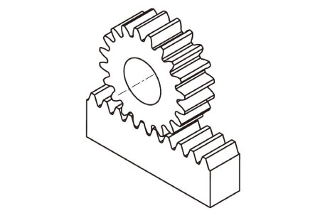
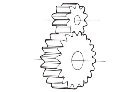
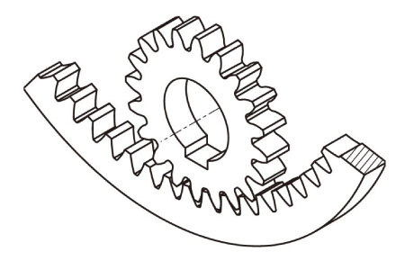
Gear Rack
Teeth are cut on plain plate or round bar. Racks can be thought of as cylindrical gears whose pitch radii are infinite.
The pinions are ordinary cylindrical gears paired with racks.
Used to convert rotary motion to linear motion or vice versa.

"You can easily interchange rotary motion and linear motion by pairing a rack and a cylindrical gear !"
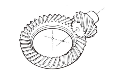
Now let’s look at the types and characteristics of gears for intersecting shafts. (Table 1-6)
Table 1-6 Types and characteristics of gears for intersecting shafts
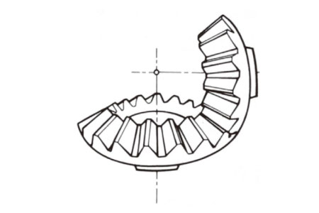
Straight bevel gears
Gears whose tooth traces are straight, umbrella-like, and coincide with the linear generatrix of the pitch cone.
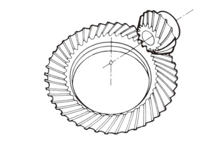
Spiral bevel gears
Bevel gears whose tooth traces are curved.
Better in strength and quietness because of larger contact ratio compared to straight bevel gears, just as in the case of cylindrical gears.
Here are the types and characteristics of gears for skewed shafts. (Table 1-7)
Table 1-7 Types and characteristics of gears for skewed shafts
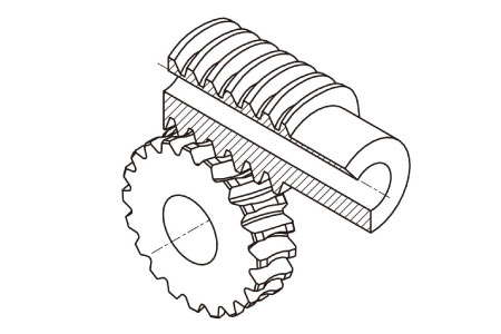
Cylindrical worm gears
General term of gears that are composed of a worm and a meshing worm wheel. Provides large speed reduction ratio in one stage.
While machine efficiency is remarkably reduced compared to other gears due to friction of sliding contact, however, noise generated by meshing is less.
When speed reduction ratio is 1/40 or more, gears can be driven by the worm, but not from the worm wheel, thus giving irreversibility (also called self-locking feature). Sometimes it is possible to drive by the worm wheel due to vibration.
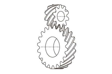
Screw gears
A pair of cylindrical gears is used to transmit motion between skewed shafts. Used in mechanisms under light loads.
Hypoid gears
A pair of conical gears which transmit motion between non-intersecting shafts.
While speed reduction ratio of hypoid gears is generally about 1/10, high ratio hypoid gears provide s high speed reduction ratios and have the possibility of having irreversibility.

"Gears with irreversibility!? Amazing !"
In the designing process, it is common to decide the layout of the two shafts before choosing the gear type. However, designers should consider that the cost of gears varies by the shaft layout as below.
1. Gears for parallel shafts (Cheap)
2. Gears for intersecting shafts
3. Gears for skewed shafts(Expensive)
We discussed gear functions as machine elements, and types and characteristics of gears in this section.
Next time, we will explain the principle of the speed ratio, one of the most crucial element of designing mechanisms with gears. (To be continued…)
Related links :
了解齿轮种类和两轴的关系
DISCLAIMER
The purpose of writing this article was to educate the readers with the elementary level of gear technology.
We hope that the actual design and manufacturing of gears and machinery utilizing gears are done with sufficient technical and specialized considerations under the user's full responsibility.
We disavow any liability and will not compensate for any direct or indirect damages caused by the gears designed by the users who read this article.