


- TOP >
- Gear Knowledge >
- The first step of mechanism design using gears >
- Know about gear transmission torque
1. Gear functions
Here is the list of gear functions for mechanism designs. (Table 3-1)
Table 3-1 Gear functions| Characteristic functions of gears | Explanation |
| Change direction of rotating shaft | (already explained) |
| Convert rotary motion to linear motion | (already explained) |
| Change rotational direction (clockwise / counterclockwise) | (already explained) |
| Change the number of rotations (speed up / down) | (already explained) |
| Change turning force (increase / decrease torque) | See this chapter |
You can increase or decrease a gear’s torque (turning force) by changing the number of rotations.
2. Definition of torque (turning force)
Torque is the turning force when load F (N) is applied at a distance L (mm) away from the center of rotation. Torque T is expressed as the following formula in N・mm (Newton millimeter). (Figure 3-1)
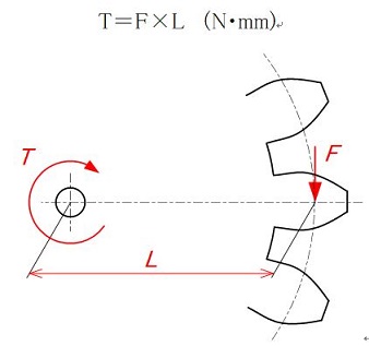
Figure 3-1 Torque
Torque T becomes larger as L (the distance from the center of rotation) becomes longer even if load F is small. On the other hand, torque T becomes larger as load F is increased even if L (the distance from the center of rotation) is short.
In other words, torque T is the factor determined by L (the distance from the center of rotation) and load F.
3. How to determine torque transmission (without regard to machine efficiency)
A gear’s transmission torque changes as it increases or decreases speed. Generally, by reducing the speed, a small torque at the input side is transmitted as a larger torque at the output side. The calculation of torque depends on the number of teeth. Let me explain with a diagram using pitch circle diameters.
The torque is calculated as follows:
- Obtain load F of the meshing point (at the radius of the pitch circle of Gear A) of the input torque.
- Obtain torque of the output side from load F of the teeth’s meshing point (radius of the pitch circle of Gear B).
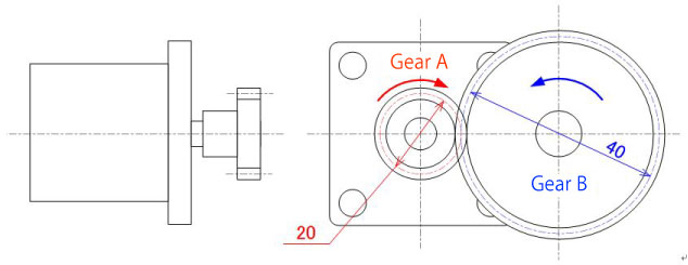
Condition
Rated torque of motor: TA=600N·mm (0.6N·m)
Gear A's pitch circle diameter φ20
Gear B's pitch circle diameter φ40
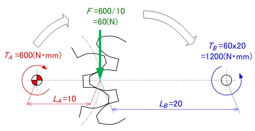
Torque transmission calculation
Load of Gear A'S meshing point: F=TA/LA=60(N)
Output side's torque: TB=F×LB=60(N)×20(mm)=1200(N·mm)
Figure 3-2 Diagram of gear’s torque transmission calculation
As you can see from Figure 3-2, by reducing the output shaft speed from the input shaft by 1/2, the output torque increases by a factor of 2.
4. Consideration of machine efficiency
As shown in the previous chapter, you can calculate a gear’s number of rotations by the number of teeth.
However, you cannot calculate a gear's transmission torque simply as shown previously because of the following reasons:
- Heat is produced by meshing teeth and energy is lost.
- Hammering sound is produced by meshing teeth and energy is lost.
Therefore, the torque (turning force) is reduced by as much as the energy is lost as above.
The ratio of input to output forces of gears is called “machine efficiency” and its approximate value is known according to the gear type. (Table 3-2)
| Relationship of two shafts | Gear name | Machine efficiency η (%) |
|---|---|---|
| parallel shaft | spur gear |
98.0 - 99.5 * Efficiency of helical gear is less than spur gear as teeth are inclined and force is created in the thrust direction. |
| helical gear | ||
| double helical gear | ||
| internal gear | ||
| rack | ||
| helical rack | ||
| intersecting shaft | straight bevel gear | 98.0 - 99.0 |
| spiral bevel gear | ||
| skewed shaft | worm gear | 30.0 - 90.0 |
| screw gear | 70.0 - 95.0 |
Note) The efficiency shown above is the transmission efficiency of gears without regard to the loss in bearings or agitation of grease.
The gear efficiency shown above are the values when gears are installed properly. If incorrectly installed, such as deviation in the intersection point of bevel gears, efficiency will decrease.

"Never forget about machine efficiency when calculating torque !"
5. Transmission torque calculation (including machine efficiency)
Now, let’s see the torque calculation formula including machine efficiency η. (Figure 3-3)
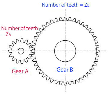
When gear A's input torque is TA, and machine efficiency is η, torque TB that is transmitted to gear B increases as efficiency η rises.
TB=η(ZB/ZA)× TA
When gear B's input torque is TB, torque TA that is transmitted to gear A decreases as efficiency η falls.
TA=η(ZA/ZB)× TB
Figure 3-3 Calculation formula of transmission torque
Exercise problem for transmission torque (1)
Calculate the torque transmitted to driven gear (B). Assume the gear type to be spur gears.
Symbol in Figure 3-4 represents the drive gear.
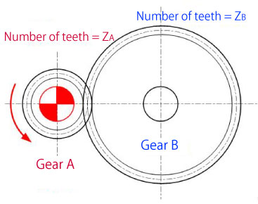
[Condition]
Number of teeth: ZA=20, ZB=40
Drive gear A's torque: TA=600 (N·mm)
Machine efficiency η: Set to 0.99 as spur gears are used.
[Answer]
Torque transmitted to gear B
TB=η(ZB/ZA)×TA
= 0.99(40/20)×600=1188(N·mm)
Figure 3-4 Exercise problem for transmission torque (1)
Exercise problem for transmission torque (2)
Calculate the torque transmitted to worm wheel B. (Figure 3-5)
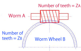
[Condition]
Number of teeth: ZA=1, ZB=30
Worm A's torque: TA=600 (N·mm)
Machine efficiency η: Set to 0.3 as worm gears are used.
[Answer]
Torque transmitted to worm wheel B
TB=η(ZB/ZA)×TA=0.3(30/1)×600
= 5400(N·mm)
Figure 3-5 Exercise problem for transmission torque (2)
Exercise problem for transmission torque (3)
Calculate the torque transmitted to driven gear (C). Assume the gear type to be helical gears.
Symbolin Figure 3-6 represents the drive gear.
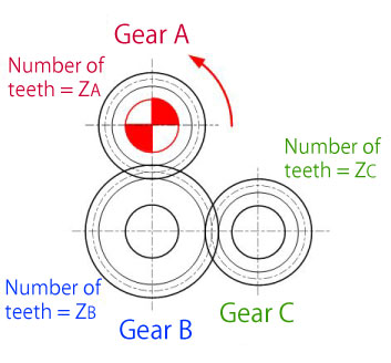
[Condition]
Number of teeth: ZA=20, ZB=30, ZC=20
Drive gear A's torque: TA=500 (N·mm)
Machine efficiency η: Set to 0.98 as helical gears are used.
[Answer]
Torque transmitted to gear B
TB=η(ZB/ZA)×TA
=0.98(30/20)×500=735(N·mm)
Torque transmitted to gear C
TC=η(ZB/ZC)×NB
=0.98(20/30)×735=480.2(N·mm)
Figure 3-6 Exercise problem for transmission torque (3)

"Just like the number of rotations, the number of teeth of the first and last gears determines the torque of a single stage gear, but the torque is reduced as machine efficiency is affected by the number of intermediate gears !"
Exercise problem for transmission torque (4)
Calculate the torque transmitted to driven gear (D). Assume the gear type to be helical gears.
Symbolin Figure 3-7 represents the drive gear.
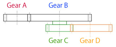
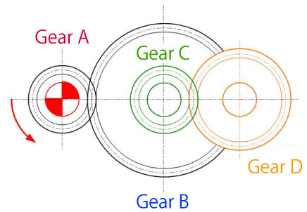
[Condition]
Number of teeth: ZA=20, ZB=40, ZC=20, ZD=30
Drive gear A's torque: TA=400 (N·mm)
Machine efficiency η: Set to 0.98 as helical gears are used.
[Answer]
Torque transmitted to gear B
TB=η(ZB/ZA)×TA
=0.98(40/20)×400=784(N·mm)
Torque transmitted to gear C
TC=TB=784(N·mm)...as being on the same shaft
Torque transmitted to gear D
TD=η(ZD/ZC)×TC
=0.98(30/20)×784=1152.5(N·mm)
Figure 3-7 Exercise problem for transmission torque (4)
When starting a mechanism design using gears, it is important to be conscious of machine efficiency. The mechanism designed without considering machine efficiency may not satisfy specifications because of torque shortage.
We discussed that machine efficiency influences gear’s transmission torque depending on the gear types and the number of meshing.
Next we will explain parameters that determine gear shapes when designing gears.
(To be continued...)
*Illustration: KAOSUN
DISCLAIMER
The purpose of writing this article was to educate the readers with the elementary level of gear technology.
We hope that the actual design and manufacturing of gears and machinery utilizing gears are done with sufficient technical and specialized considerations under the user's full responsibility.
We disavow any liability and will not compensate for any direct or indirect damages caused by the gears designed by the users who read this article.
Related Links :
Know about parameters that determine gear shapes
了解齿轮的扭矩传递