


There are direct and indirect methods for measuring tooth thickness. In general, there are three methods :
- Chordal tooth thickness measurement
- Span measurement
- Over pin or ball measurement
5.1 Chordal Tooth Thickness Measurement
This method employs a tooth caliper that is referenced from the gear’s tip diameter. Thickness is measured at the reference circle. See Figure 5.1.
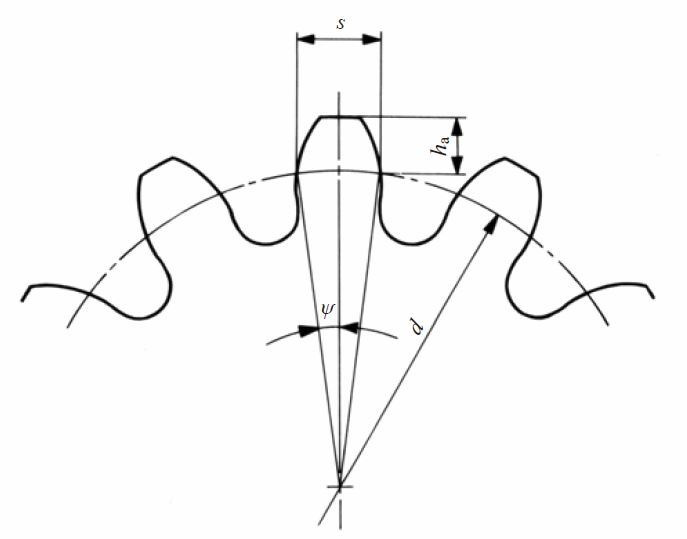
Fig.5.1 Chordal tooth thickness method
(1)
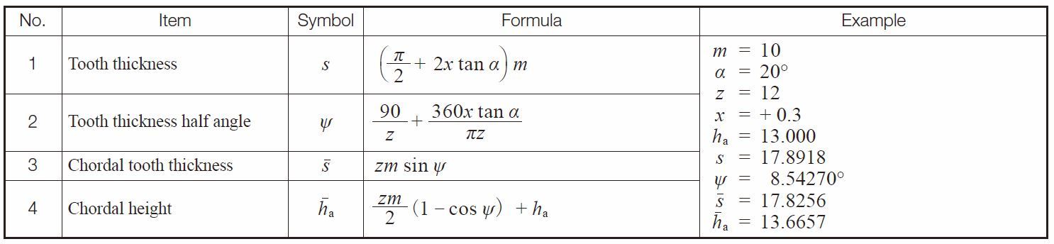
Spur Gears
Table 5.1 presents equations for each chordal tooth thickness measurement.
Table 5.1 Equations for spur gear chordal tooth thickness
(2) Spur
Gear Racks
and Helical Gear Racks
The governing equations become simple since the rack tooth profile is trapezoid, as shown in Table 5.2.
Table 5.2 Chordal tooth thickness of racks
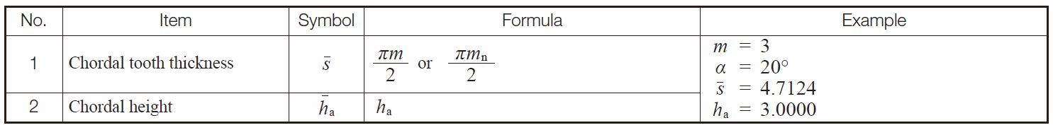
NOTE : These equations are also applicable to helical racks.
(3) Helical Gears
The chordal tooth thickness of
helical gears
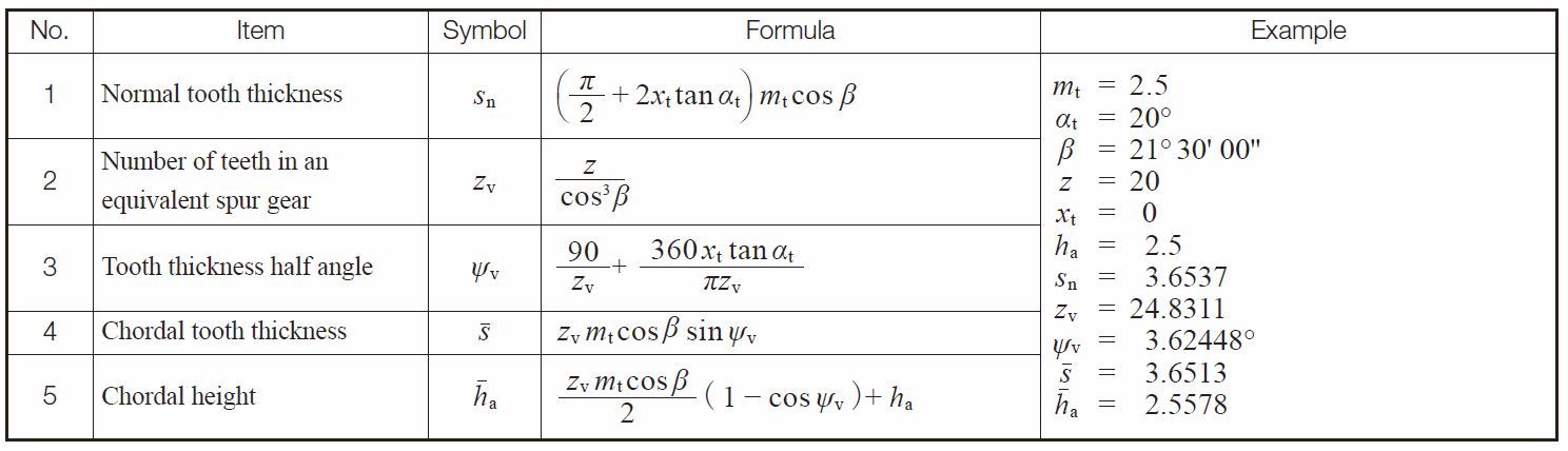
should be measured on the normal plane basis as shown in Table 5.3. Table 5.4 presents the equations for chordal tooth thickness of helical gears in the transverse system.
Table 5.3 Equations for chordal tooth thickness of helical gears in the normal system
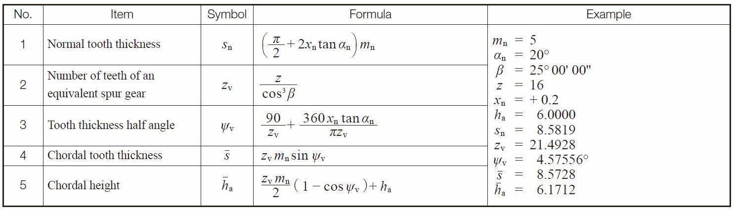
Table 5.4 Equations for chordal tooth thickness of helical gears in the transverse system
(4) Bevel Gears
Table 5.5 shows the equations for chordal tooth thickness of a Gleason straight
bevel gear
. Table 5.6 shows the same of a standard straight bevel gear. Table 5.7 the same of a Gleason spiral bevel gear.
Table 5.5 Equations for chordal tooth thickness of Gleason straight bevel gears
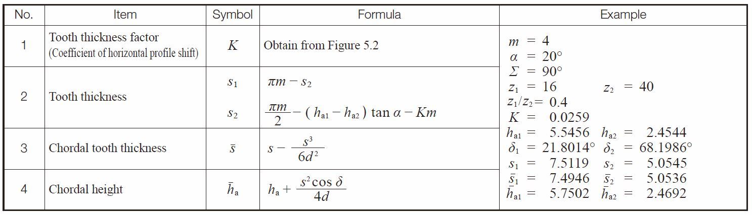
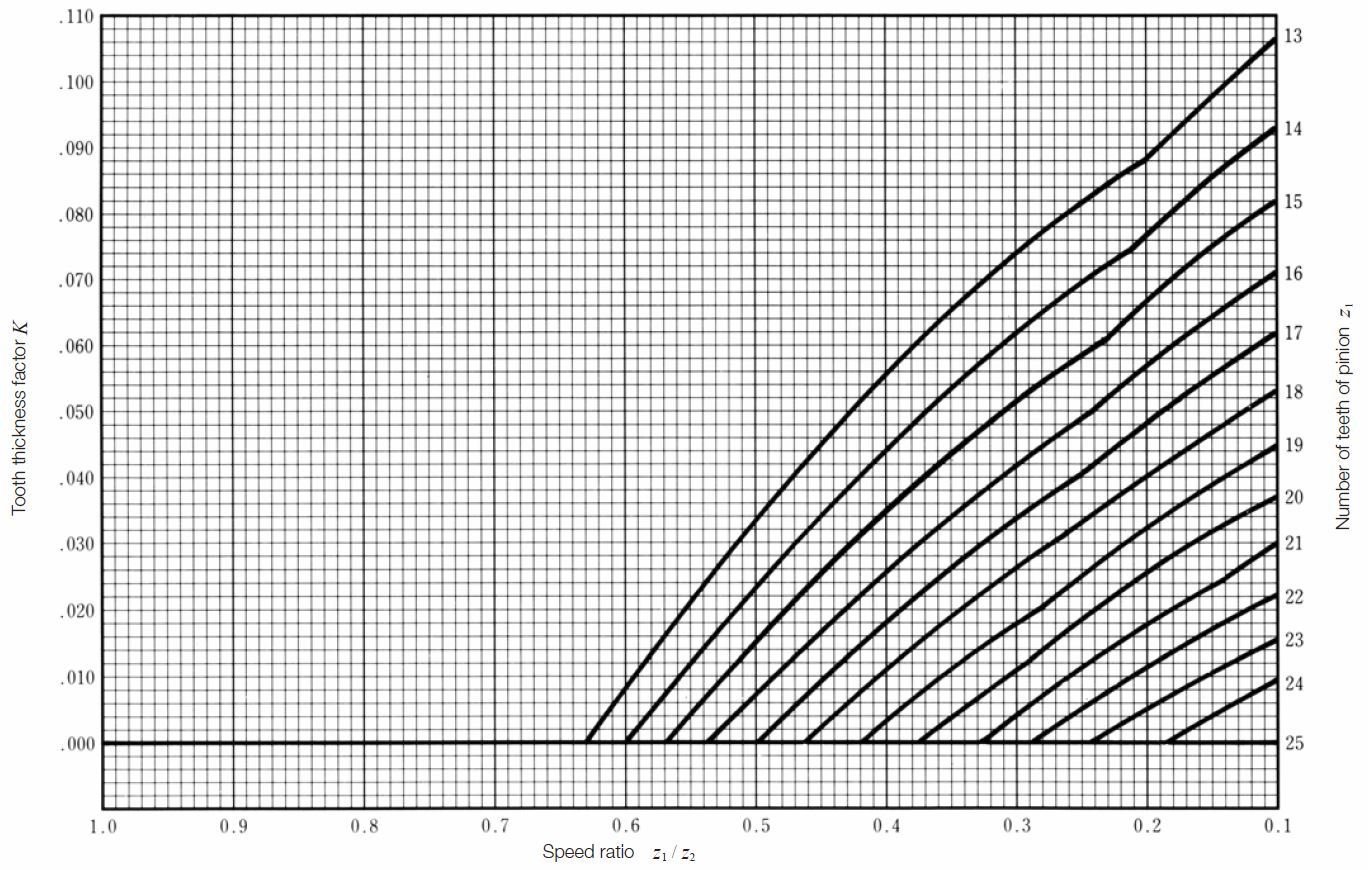
Fig.5.2 Chart to determine the tooth thickness factor k for Gleason straight bevel gear
Table 5.6 Equations for chordal tooth thickness of standard straight bevel gears
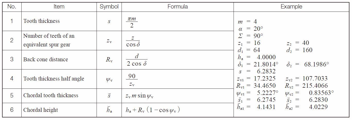
If a straight bevel gear is cut by a Gleason straight bevel cutter, the tooth angle should be adjusted according to :
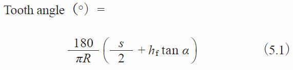
This angle is used as a reference in determining the tooth thickness, s, when setting up the gear cutting machine.
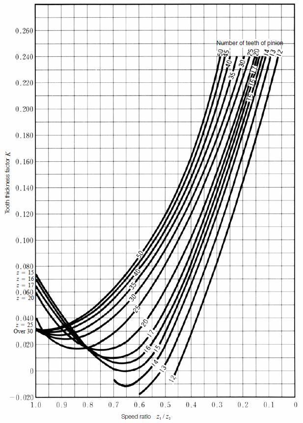
Fig.5.3 Chart to determine the tooth thickness factor k for Gleason spiral bevel gears
Table 5.7 Equations for chordal tooth thickness of Gleason spiral bevel gears
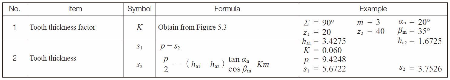
The calculations of chordal tooth thickness of a Gleason spiral bevel gear are so complicated that we do not intend to go further in this presentation.
(5) Worm Gear Pair
Table 5.8 presents equations for chordal tooth thickness of axial module
worm gear
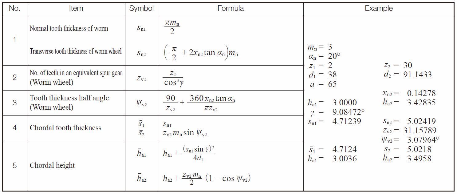
pairs. Table 5.9 presents the same of normal module worm gear pairs.
Table 5.8 Equations for chordal tooth thickness of an axial module worm gear pair
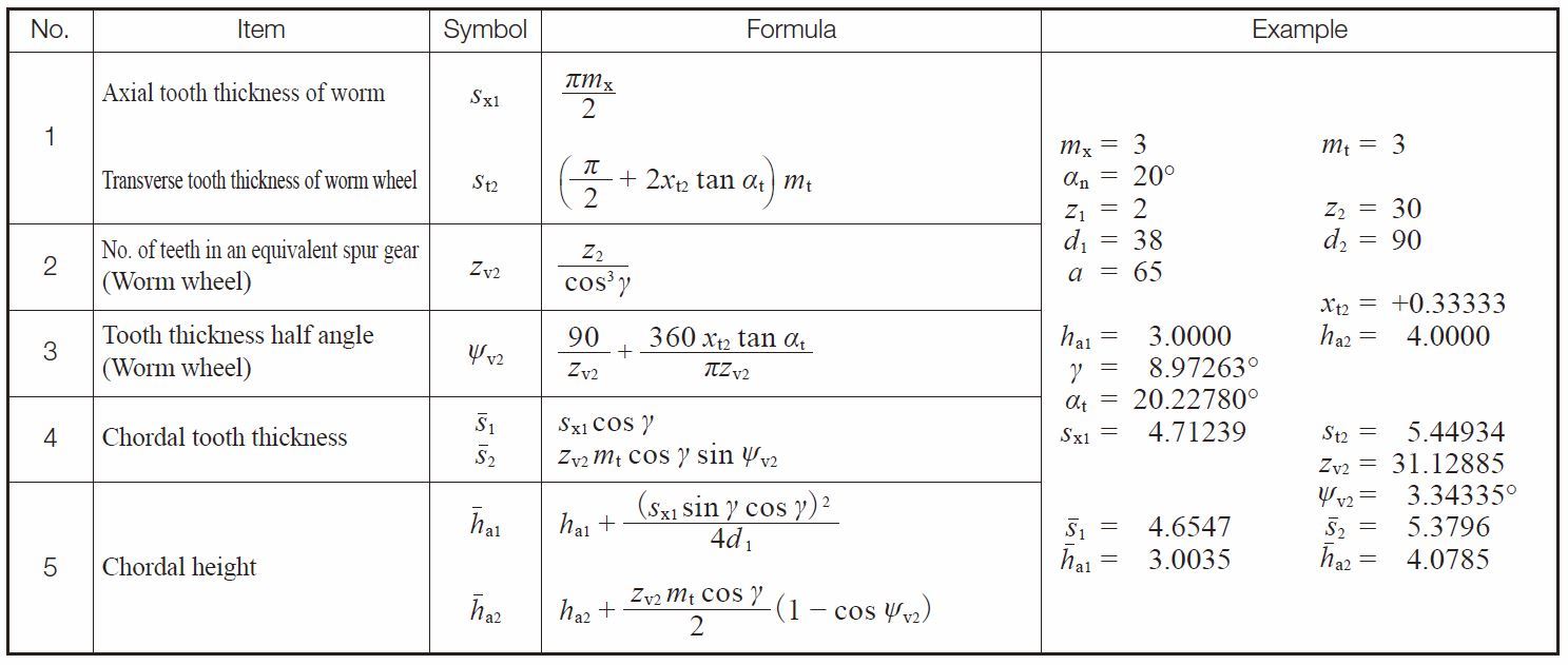
Table 5.9 Equations for chordal tooth thickness of a normal module worm gear pair
5.2 Span Measurement of Teeth
Span measurement of teeth, W, is a measure over a number of teeth, k, made by means of a special tooth thickness micrometer. The value measured is the sum of normal tooth thickness on the base circle , sbn, and normal pitch, pbn(k – 1). See Figure 5.4.
(1) Spur and Internal Gears
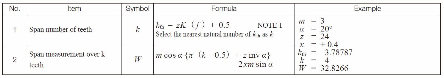
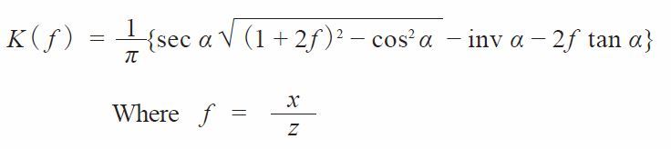
The applicable equations are presented in Table 5.10.
Table 5.10 Span measurement calculations for spur and internal gear teeth
NOTE :
 (5.2)
(5.2)
Figure 5.4 shows the span measurement of a spur gear. This measurement is on the outside of the teeth. For internal gears the tooth profile is opposite to that of the external spur gear. Therefore, the measurement is between the inside of the tooth profiles.
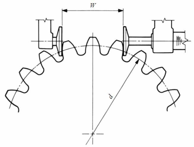
Fig.5.4 Span measurement over k teeth (spur gear)
(2) Helical Gears
Table 5.11 and 5.12 present equations for span measurement of the normal and the transverse systems, respectively, of helical gears.
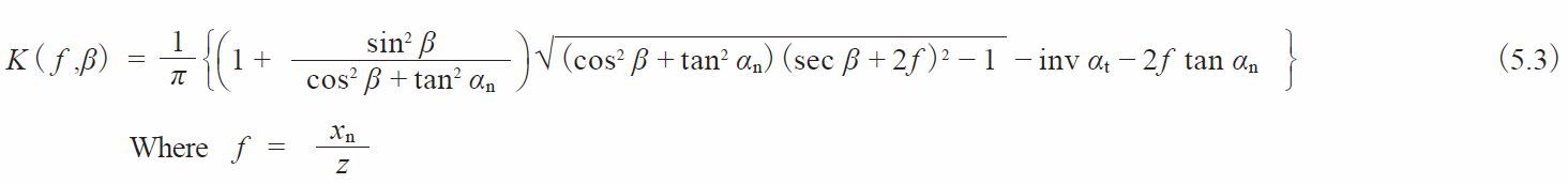
Table 5.11 Equations for the span measurement of normal system helical gears
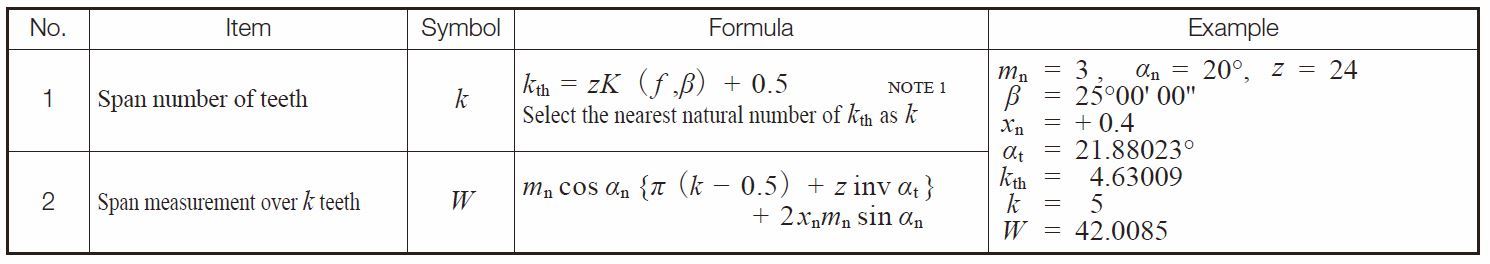
NOTE :
See page 655 to find the figures showing how to determine the number of span number of teeth of a profile shifted spur and helical gears.
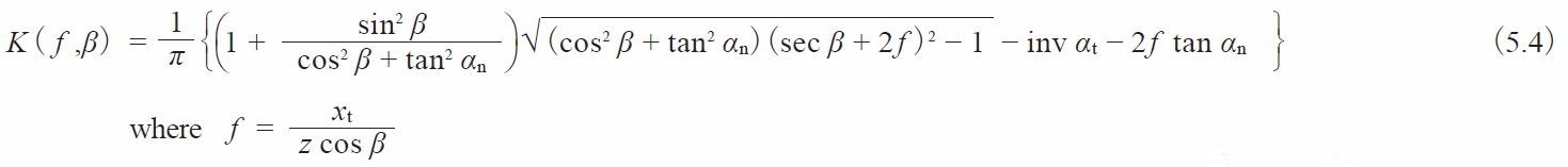
Table 5.12 Equations for span measurement of transverse system helical gears
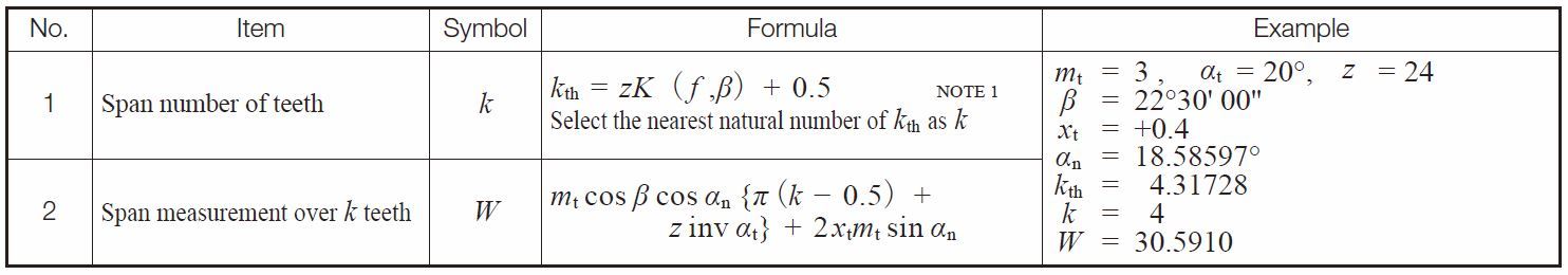
NOTE :
There is a requirement of a minimum facewidth to make a helical gear span measurement. Let b min be the minimum value for facewidth. See Fig. 5.5.
![]()
Where βb is the helix angle at the base cylinder,
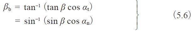
From the above, we can determine Δb > 3 mm to make a stable measurement of W.
Refer to page 656 to 659 to review the data sheet “Span Measurement Over k Teeth of Standard Spur Gears” (Pressure Angle: 20 degrees, 14.5 celsius).
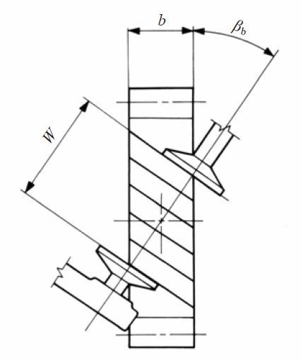
Fig.5.5 Facewidth of helical gear
5.3 Measurement Over Rollers (or generally called over pin/ball measurement)
As shown in Figure 5.6, measurement is made over the outside of two pins that are inserted in diametrically opposite tooth spaces, for even tooth number gears, and as close as possible for odd tooth number gears. The procedure for measuring a rack with a pin or a ball is as shown in Figure 5.8 by putting pin or ball in the tooth space and using a micrometer between it and a reference surface.
Internal gears are similarly measured, except that the measurement is between the pins. See Figure 3.9. Helical gears can only be measured with balls. In the case of a worm, three pins are used, as shown in Figure 5.10. This is similar to the procedure of measuring a screw thread.
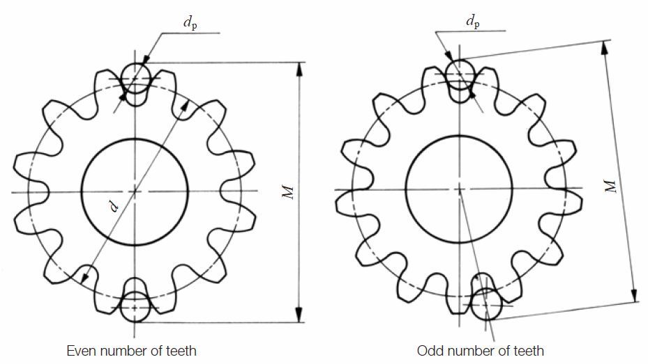
Fig. 5.6 Over pin (ball) measurement
(1) Spur Gears
In measuring a standard gear, the size of the pin must meet the condition that its surface should have a tangent point at the standard
pitch circle
. When measuring a shifted gear, the surface of the pin should have a tangent point at the d + 2xm circle. Under the condition mentioned above, Table 5.13 indicated formulas to determine the diameter of the pin (ball) for the spur gear in Figure 5.7.
Table 5.13 Equations for calculating ideal pin diameters
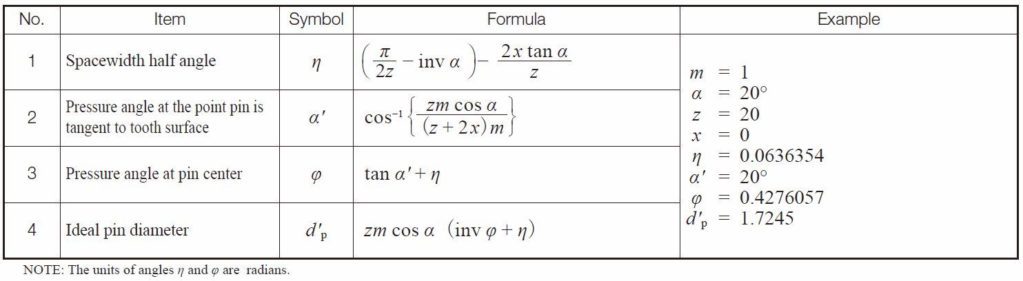
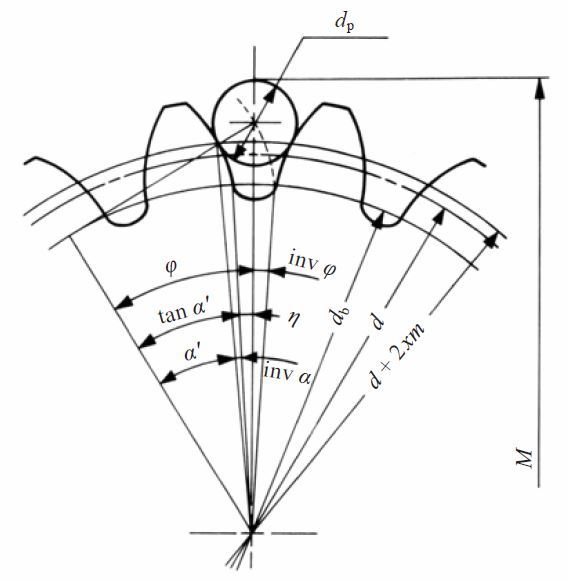
Fig.5.7 Over pins measurement of spur gear
The ideal diameters of pins when calculated from the equations of Table 5.13 may not be practical. So, in practice, we select a standard pin diameter close to the ideal value. After the actual
diameter of pin dp is determined, the over pin measurement M can be calculated from Table 5.14.
Table 5.14 Equations for over pins measurement of spur gears
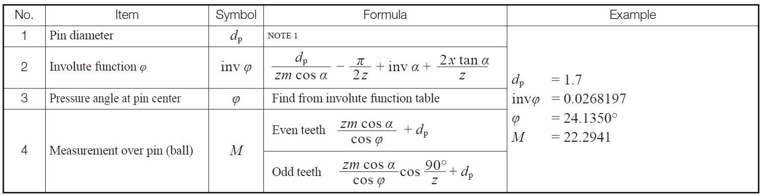
NOTE : The value of the ideal pin diameter from Table 5.13. or its approximate value, is applied as the actual diameter of pin dp here.
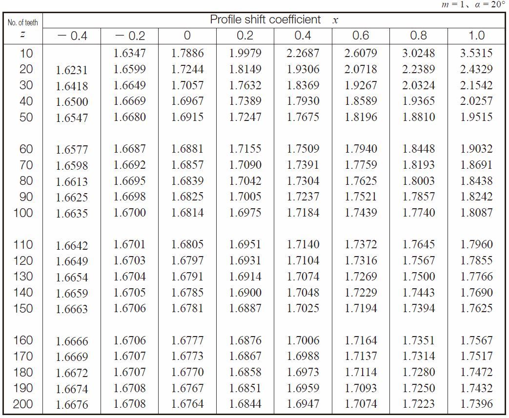
Table 5.15 is a dimentional table under the condition of module m = 1 and pressure angle α = 20° with which the pin has the tangent point at d + 2xm circle.
Table 5.15 The size of pin which has the tangent point at d + 2xm circle for spur gears
(2) Spur Racks and Helical Racks
In measuring a rack, the pin is ideally tangent with the tooth flank at the pitch line. The equations in Table 5.16A can, thus, be derived. In the case of a helical rack, module m, and pressure angle α, in Table 5.16A, can be substituted by normal module mn, and normal pressure angle αn, resulting in Table 5.16B.
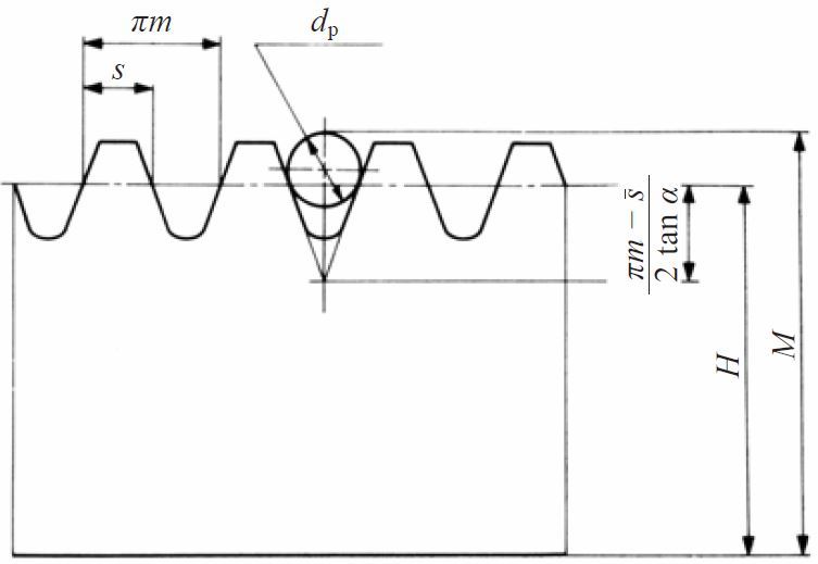
Fig. 5.8 Over pins measurement for a rack using a pin or a ball
Table 5.16A Equations for over pins measurement of spur racks
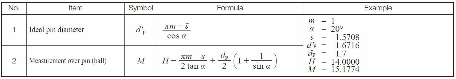
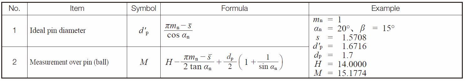
Table 5.16B Equations for Over Pins Measurement of Helical Racks
(3) Internal Gears
As shown in Figure 5.9, measuring an internal gear needs a proper pin which has its tangent point at d + 2xm circle. The equations are in Table 5.17 for obtaining the ideal pin diameter. The equations for calculating the between pin measurement, M, are given in Table 5.18.
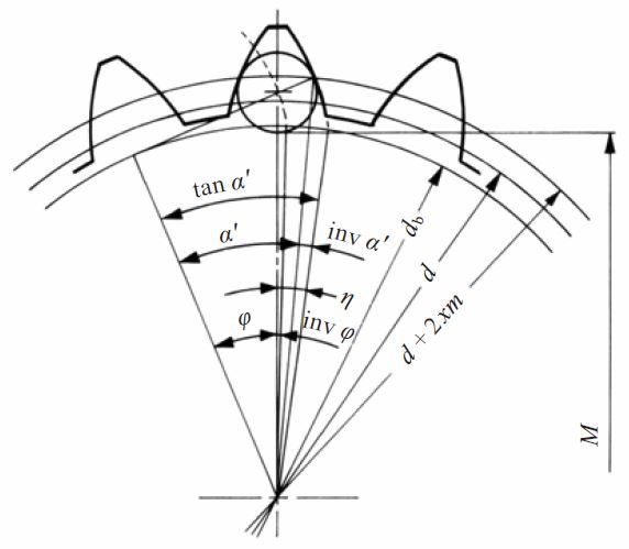
Fig. 5.9 Between pin dimension of internal gears
Table 5.17 Equations for calculating pin diameter for internal gears
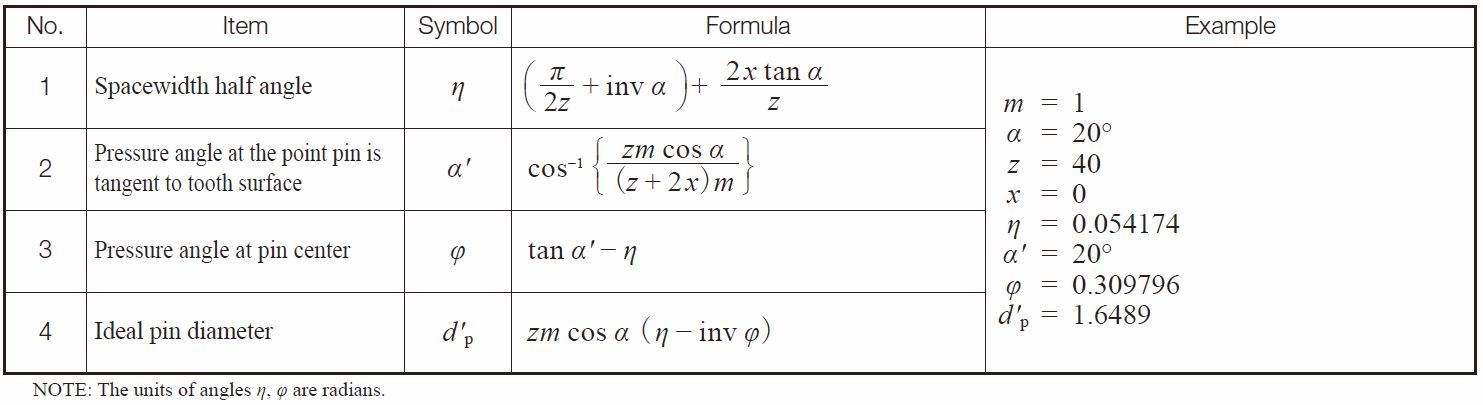
Table 5.18 Equations for between pins measurement of internal gears
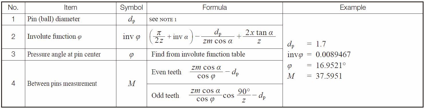
NOTE: First, calculate the ideal pin diameter. Then, choose the nearest practical actual pin size.
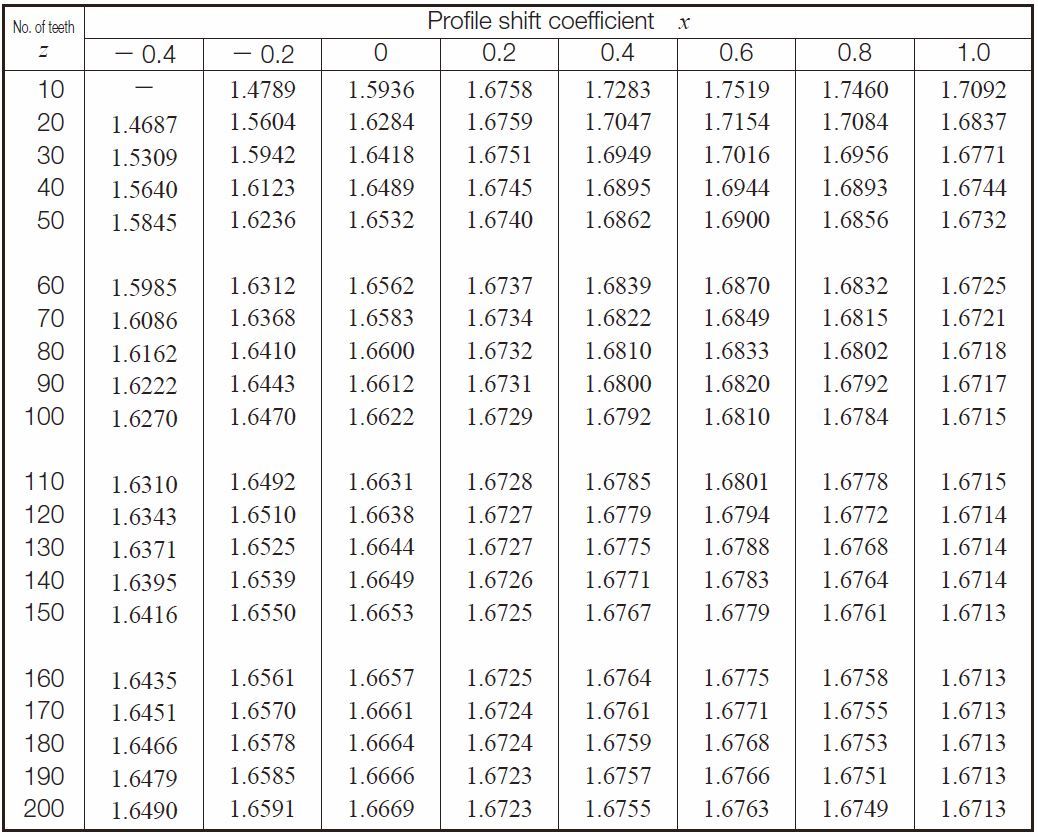
Table 5.19 lists ideal pin diameters for standard and profile shifted gears under the condition of module m = 1 and pressure angle α = 20°, which makes the pin tangent to the reference circle d + 2xm.
Table 5.19 The size of pin that is tangent at reference circle d + 2xm for internal gears
(4) Helical Gears
The ideal pin that makes contact at the d + 2xnmn reference circle of a helical gear can be obtained from the same above equations, but with the teeth number z substituted by the equivalent (virtual) teeth number zv.
Table 5.20 presents equations for driving over pin diameters. Table 5.21 presenrts equations for calculating over pin measurement for helical gears in the normal system.
Table 5.20 Equations for calculating pin diameter for helical gears in the normal system
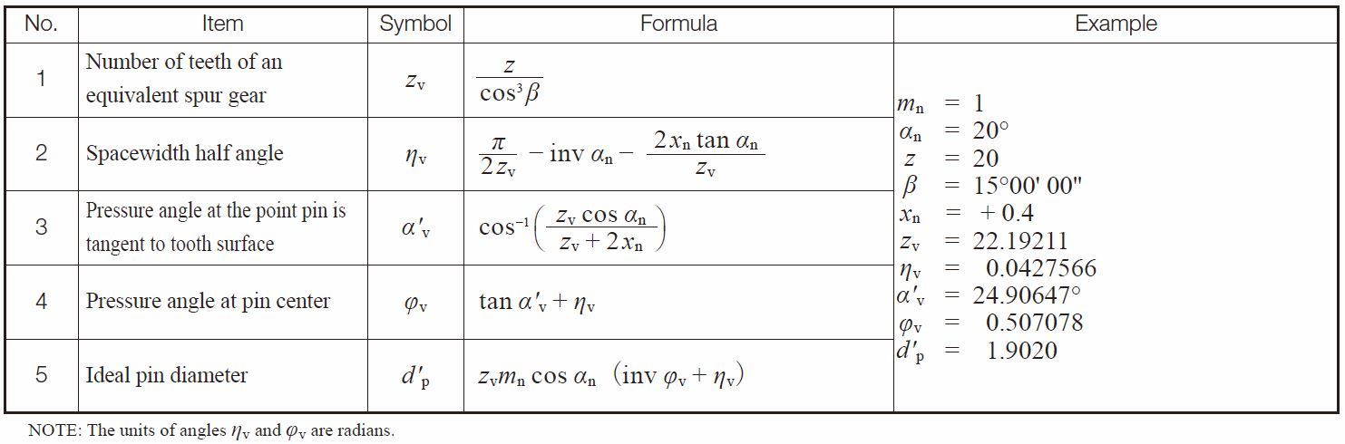
Table 5.21 Equations for calculating over pins measurement for helical gears in the normal system
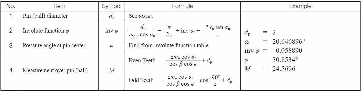
NOTE 1: The ideal pin diameter of Table 5.20, or its approximate value, is entered as the actual diameter of dp.
Table 5.22 and Table 5.23 present rquations for calculating pin measurements for helical gears in the transverse (perpendicular to axis) system.
Table 5.22 Equations for calculating pin diameter for helical gears in the transverse system
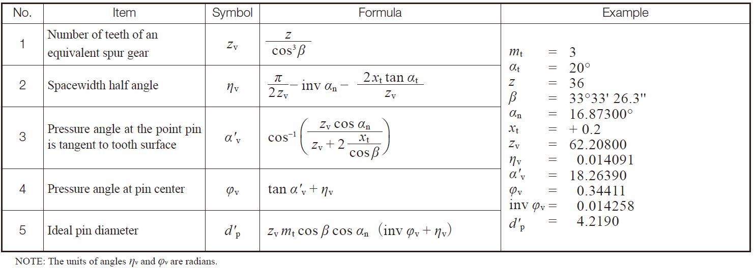
Table 5.23 Equations for calculating over pins measurement for helical gears in the transverse system

NOTE : The ideal pin diameter of Table 5.22, or its approximate value is applied as the actual diameter of pin dp here.
(5) Three Wire Method of Worm Measurement
The tooth profile of type III worms which are most popular are cut by standard cutters with a pressure angle α0 = 20°. This results in the normal pressure angle of the worm being a bit smaller than 20°. The equation below shows how to calculate a type III worm in an AGMA system.
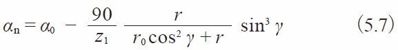
Where
r :Worm reference radius
r0 :Cutter radius
z1 :Number of threads
γ :Lead angle of worm
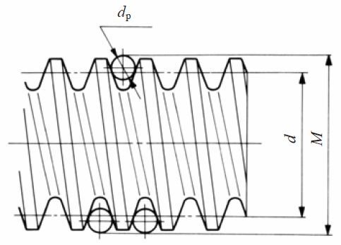
Fig. 5.10 Three wire method of a worm
The exact equation for a three wire method of type III worm is not only difficult to comprehend, but also hard to calculate precisely. We will introduce two approximate calculation methods here :
(a) Regard the tooth profile of the worm as a straight tooth profile of a rack and apply its equations.
Using this system, the three wire method of a worm can be calculated by Table 5.24.
Table 5.24 Equations for three wire method of worm measurement, (a)-1
These equations presume the worm lead angle to be very small and can be neglected. Of course, as the lead angle gets larger, the equations’ error gets correspondingly larger. If the lead angle is considered as a factor, the equations are as in Table 5.25.
Table 5.25 Equations for three wire method of worm measurement, (a)-2
(b) Consider a worm to be a helical gear.
This means applying the equations for calculating over pins measurement of helical gears to the case of three wire method of a worm. Because the tooth profile of Type III worm is not an
involute curve
, the method yields an approximation. However, the accuracy is adequate in practice.
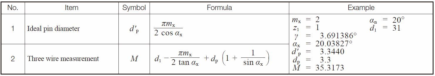
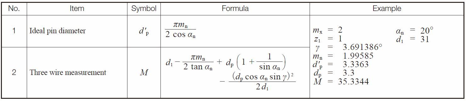
Tables 5.26 and 5.27 contain equations based on the axial system. Table 5.28 and 5.29 are based on the normal system.
Table 5.26 Equations for calculating pin diameter for worms in the axial system
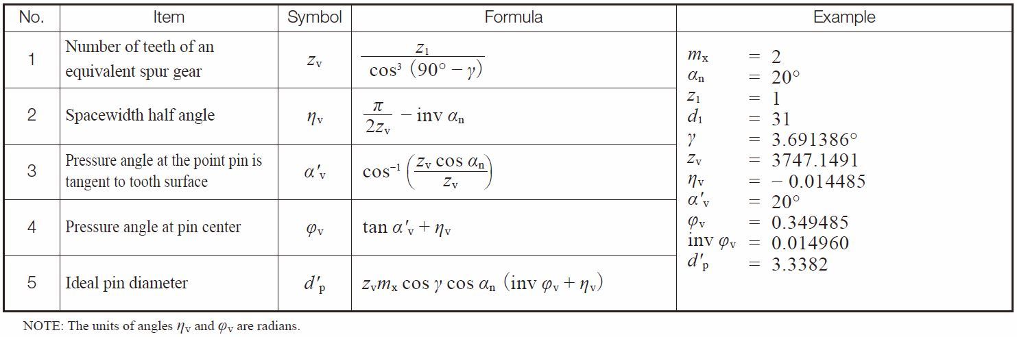
Table 5.27 Equations for three wire method for worms in the axial system
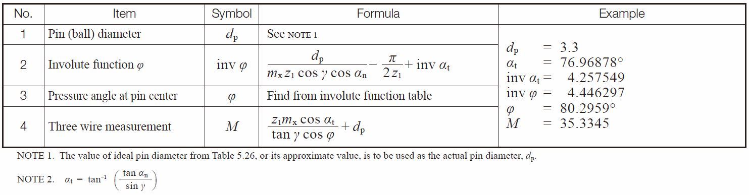
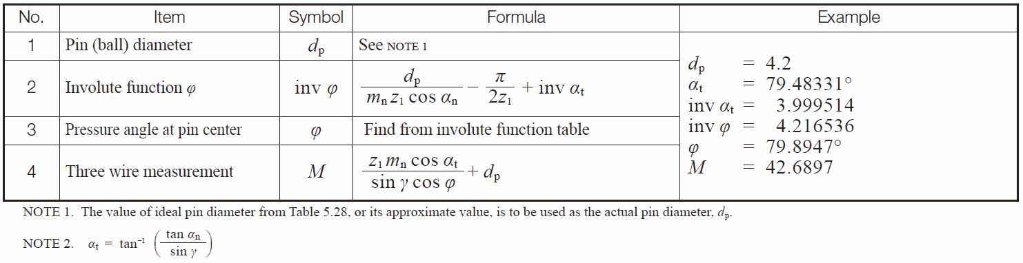
Table 5.28 and 5.29 show the calculation of a worm in the normal module system. Basically, the normal module system and the axial module system have the same form of equations. Only the notations of module make them different.
Table 5.28 Equations for calculating pin diameter for worms in the normal system
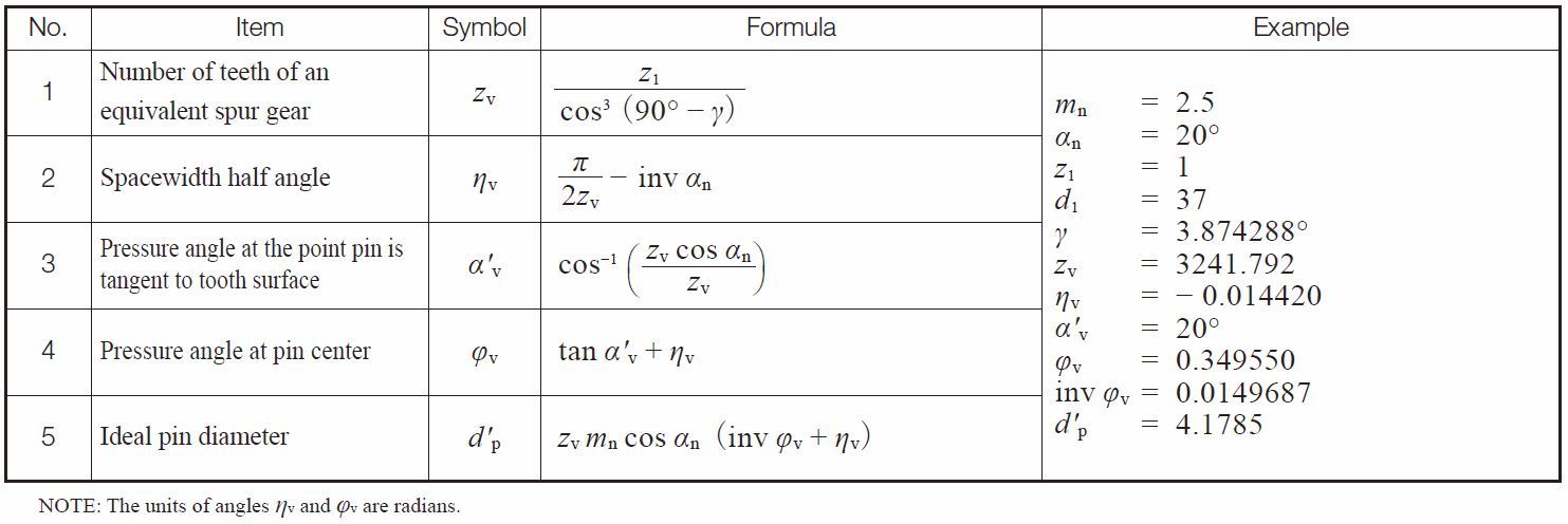
Table 5.29 Equations for three wire method for worms in the normal system
Related links :
齿轮的齿厚
Calculation of Gear Dimensions
– A page of Calculation of Gear Dimensions