


The following equations can be applied to both spur gears and helical gears, including double helical and internal gears, used in power transmission. The general range of application is:
Module m 1.5-25mm
Pitch diameter d0 25-3200mm
Tangential speed v 25m/s or less
Rotational speed n 3600rpm or less
(1) Conversion Formulas
The equations that relate tangential force at the pitch circle, Ft(kgf), power, P(kW), and torque, T(kgf・m) are basic to the calculations. The relations are:
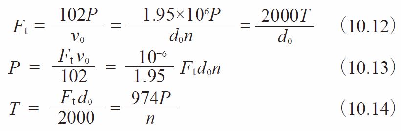
Where
v0 :Tangential speed of working pitch circle (m/s) = d0n / 19100
d0 :Working pitch diameter (mm)
n :Rotational speed (rpm)
(2) Surface Durability Equations
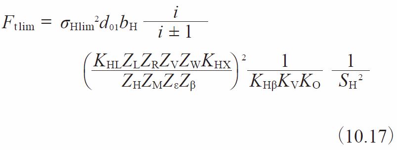
In order to satisfy the surface durability, the transmitted tangential force at the reference pitch circle, Ft, is not to exceed the allowable tangential force at the reference pitch circle, Ft lim, that is calculated taking into account the allowable Hertz stress.
![]()
At the same time, the actual Hertz stress, σH, that is calculated on the basis of the tangential force at the reference pitch circle, Ft, should not exceed the allowable Hertz stress, σHlim.
![]()
The allowable tangential force, Ft lim (kgf), at the reference pitch circle, can be calculated from Equation (10.17)
The Hertz stress σH(kgf/mm2) is calculated from Equation (10.18)
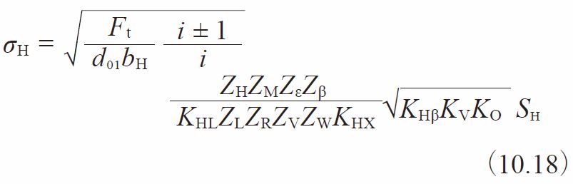
The “+” symbol in Equations (10.17) and (10.18) applies to two external gears in mesh, whereas the “-” symbol is used for an internal gear and an external gear mesh. For the case of a gear rack and a gear, the quantity i/i ±1 becomes 1.
(3) Determination of Factors
(3)-1 Effective Facewidth in Calculating Surface Strength bH(mm)
When gears with wider facewidth mate with gears with thinner facewidth, take thinner the facewidth for the calculation of surface strength bH.
When gears are end relieved, the effective facewidth should not include the relieved portions.
Supplement / Facewidth of round racks
In order to obtain the values of the allowable forces shown in the dimensional table, the calculations were made based on condition that the facewidth was:
b1 – in the case of bending strength
b2 – in the case of surface durability:
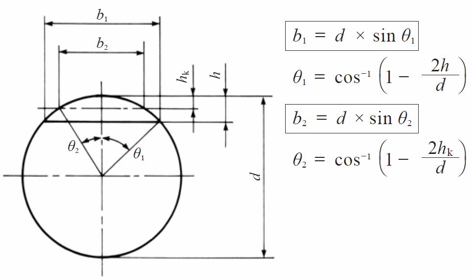
Where
hk = addendum
h = tooth depth
d = outside diameter
(3)-2 Zone Factor, ZH
The zone factor, ZH, is defined as:
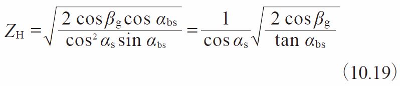
Where βg = tan-1 (tan β cos αs)
βg :Base helix angle (degrees)
αbs :Working transverse pressure angle (degrees)
αs :Transverse pressure angle (degrees)
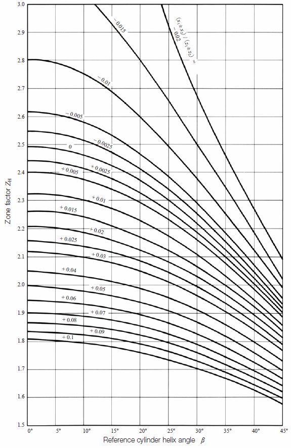
The zone factors are presented in Figure 10.2 for tooth profiles per JIS B 1701, pressure angle αn = 20°, profile shift coefficient x1 and x2, numbers of teeth z1 and z2, and helix angle β0.
Re: “±” symbol in Figure 10.2
The “+” symbol applies to external gear meshes, whereas the “-” is used for internal gear and external gear meshes.
Fig.10.2 Zone factor, ZH
(3)-3 Material Factor, ZM
The material factor, ZM is determined from:
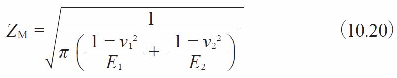
Where
ν:Poisson’s ratio
E:Young’s modulus (kgf/mm2)
Table 10.9 contains several combinations of material and their material factor, ZM.
Table 10.9 Material factor, ZM
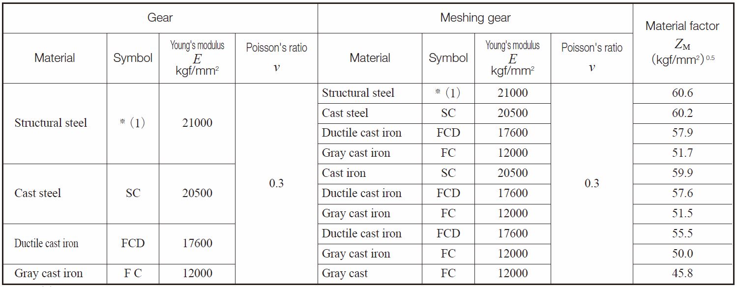
NOTE (1) Structural steels are S ~ C、SNC、SNCM、SCr、SCM etc.
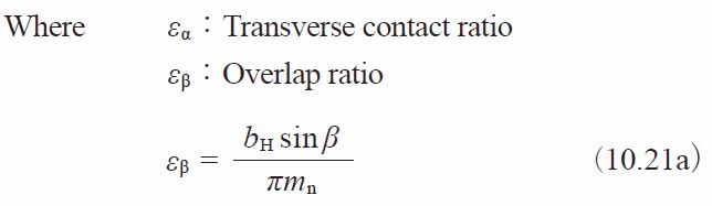
(3)-4 Contact Ratio Factor, Zε
Contact ratio factor can be determined from:
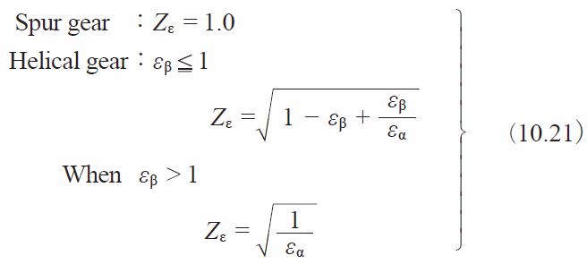
(3)-5 Helix Angle Factor, Zβ
This is a difficult parameter to evaluate. Therefore, it is assumed to be 1.0 unless better information is available.
![]()
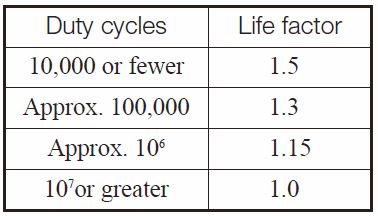
(3)-6 Life Factor, KHL
Table 10.10 indicates the life factor, KHL
Table10.10 Life factor, KHL
NOTE
1.
The duty cycle is the number meshing cycles during a lifetime.
2.
Although an idler has two meshing points in one cycle, it is still regarded as one repetition.
3.
For bidirectional gear drives, the larger loaded direction is taken as the number of cyclic loads.
When the number of cycles is unknown, KHL is assumed to be 1.0.
(3)-7 Lubricant Factor, ZL
The lubricant factor, ZL is based upon the lubricant’s kinematic viscosity at 50 degree Celsius, cSt . See Figure 10.3.
Fig. 10.3 Lubricant factor, ZL
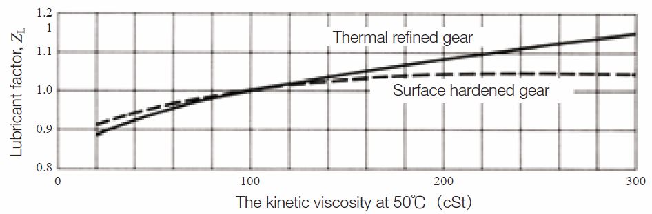
NOTE : Thermal refined gears include quenched and tempered gears and normalized gears.
(3)-8 Surface Roughness Factor, ZR
The surface roughness factor, ZR is obtained from Figure 10.4 on the basis of the average roughness Rmaxm (μm). The average roughness, Rmaxm is calculated by Equation (10.23) using the surface roughness values of the pinion and gear, Rmax1 and Rmax2, and the center distance, a, in mm.
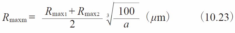
Fig.10.4 Surface roughness factor, ZR
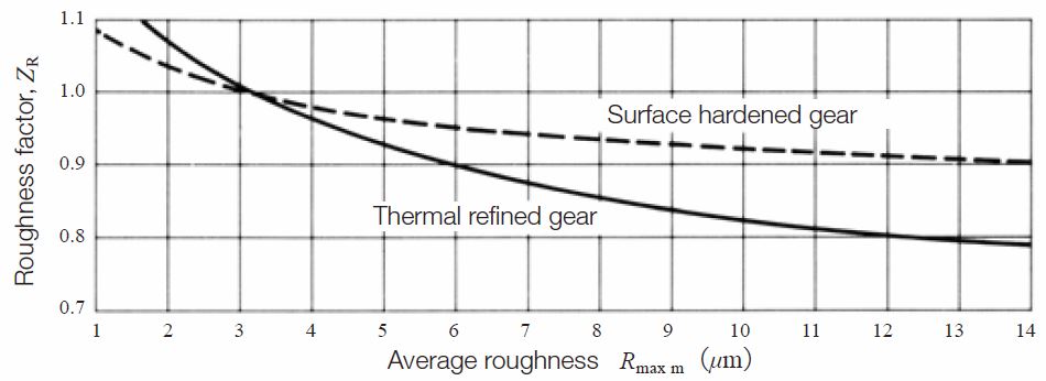
NOTE : Thermal refined gears include quenched and tempered gears and normalized gears.
(3)-9 Lubrication speed factor, ZV
The lubrication speed factor, ZV, relates to the tangential speed of the pitch circle, v (m/s) . See Fugure 10.5.
Fig.10.5 Lubrication speed factor, ZV
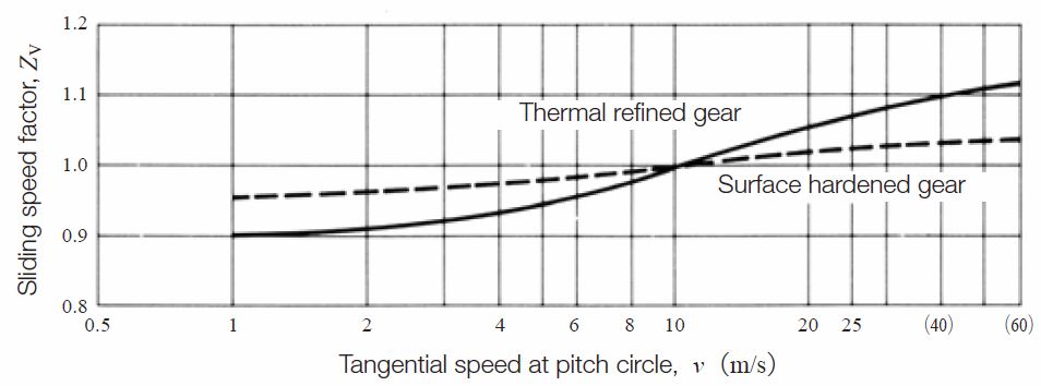
NOTE : Thermal refined gears include quenched and tempered gears and normalized gears.
(3)-10 Hardness Ratio Factor, ZW
The hardness ratio factor, ZW, applies only to the gear that is in mesh with a pinion which is quenched and ground. The hardness ratio factor, ZW, is calculated by Equation (10.24).
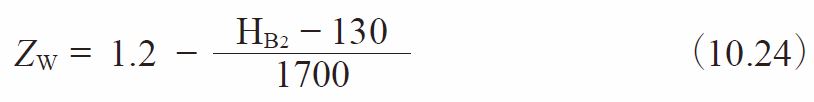
Where HB2:Brinell hardness of gear range:
130 ≦ HB2 ≦ 470
If a gear is out of this range, the ZW is assumed to be 1.0.
(3)-11 Size Factor, KHX
Because the conditions affecting this parameter are often unknown, the factor is usually set at 1.0.
![]()
(3)-12 Longitudinal Load Distribution Factor, KHβ
The longitudinal load distribution factor, KHβ, is obtainable from:
1. When tooth contact under load is not predictable:
This case relates to the method of gear shaft support, and to the ratio, b/d01, of the gear facewidth b, to the pitch diameter, d01. See Table 10.11.
Table 10.11 Longitudinal load distribution factor
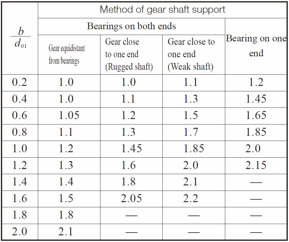
NOTE :
1. The b means effective facewidth of spur and helical gears. For double helical gears, b is facewidth including central groove.
2. Tooth contact must be good under no load.
3. The values in this table are not applicable to gears with two or more mesh points, such as an idler.
2. When tooth contact under load is good.
When tooth contact under load is good, and in addition, when a proper running-in is conducted, the factor is in a narrower range, as specified below:
![]()
(3)-13 Dynamic Load Factor, KV
Dynamic load factor, KV, is obtainable from Table 10.3 according to the gear’s precision grade and pitch circle tangential speed, v0.
(3)-14 Overload Factor, KO
The overload factor, KO, is obtained from either Equation (10.12) or Table 10.4.
(3)-15 Safety Factor for Pitting, SH
The causes of pitting involves many environmental factors and usually is difficult to precisely define. Therefore, it is advised that a factor of at least 1.15 be used.
(3)-16 Allowable Hertz Stress, σHlim
The values of allowable Hertz stress, σHlim, for various gear materials are listed in Tables 10.12 through 10.16. Values for hardness not listed can be estimated by interpolation. Surface hardness is defined as the hardness in the pitch circle region.
Table 10.12 Gears without surface hardening – allowable Hertz stress
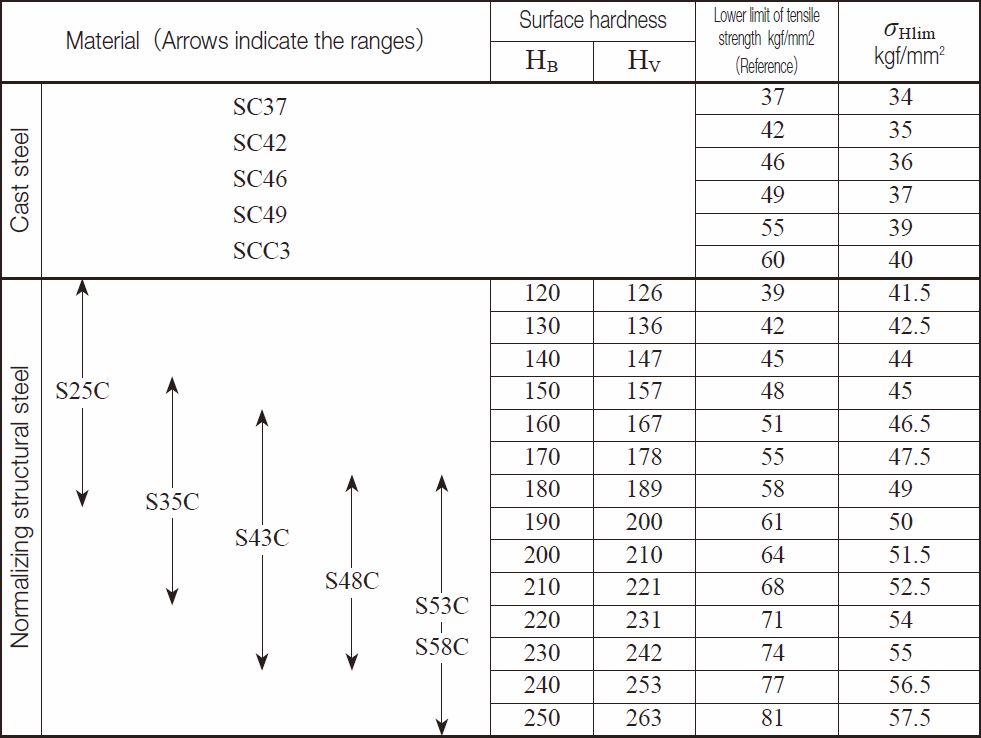
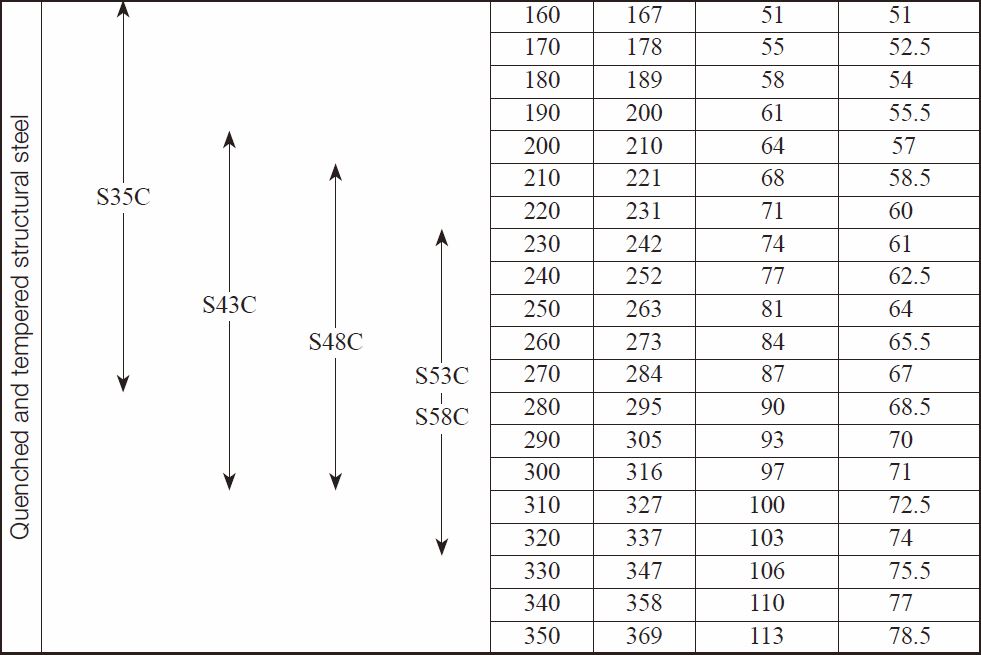
Table 10.12 Gears without surface hardening – allowable Hertz stress
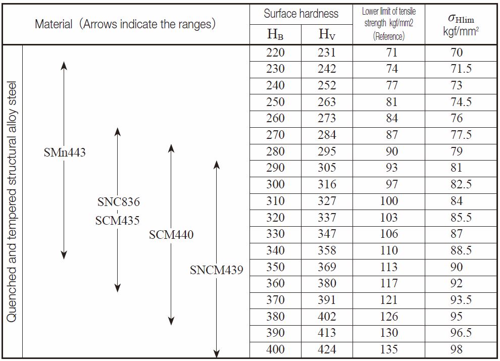
Table 10.13 Gears with induction hardening – allowable Hertz stress
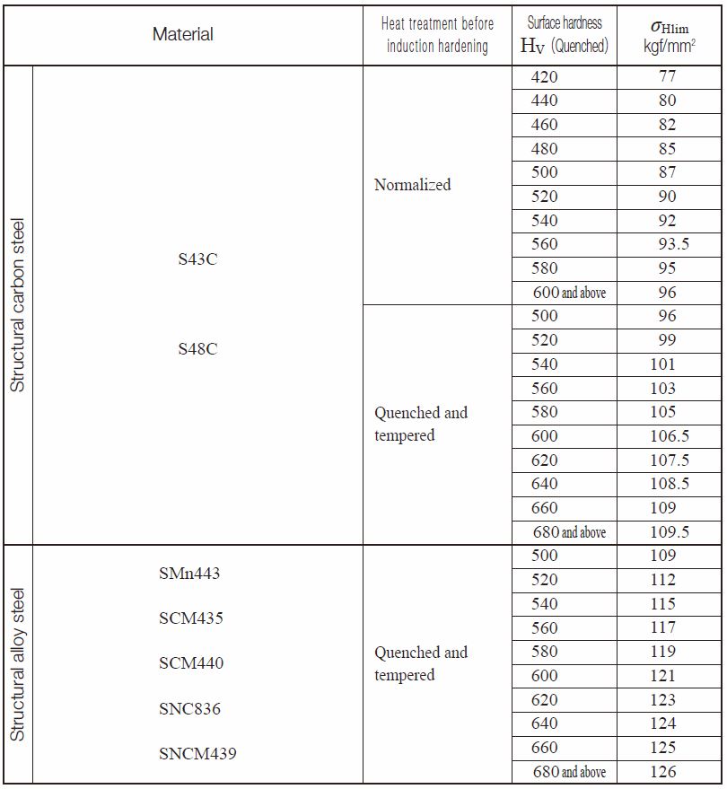
Table 10.14 Carburized and quenched gears – allowable Hertz stress
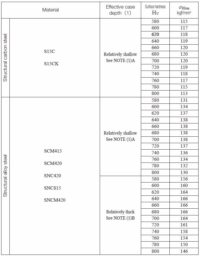
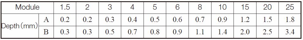
NOTE (1)
Gears with thin effective case depth have “A” row values in the following Table.
For thicker depths, use “B” values.
The effective case depth is defined as the depth which has the hardness greater than HV513 (HRC50).
The effective case depth of ground gears is defined as the residual layer depth after grinding to final dimensions.
REMARKS :
For two gears with large numbers of teeth in mesh, the maximum shear stress point occurs in the inner part of the tooth beyond the carburized depth.
In such a case, a larger safety factor, SH, should be used.
Table 10.15 Gears with nitriding – allowable Hertz stress (1)
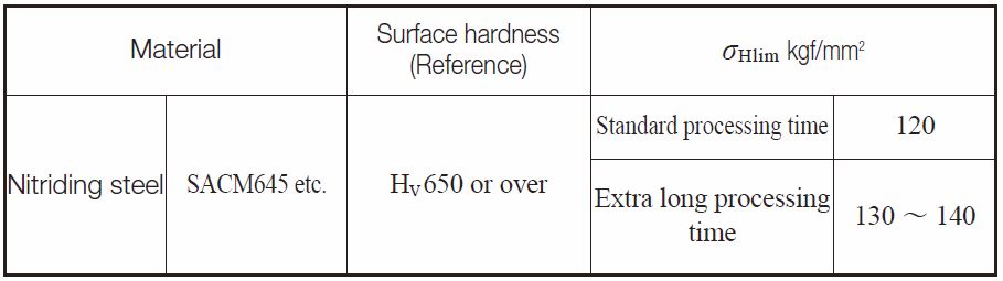
NOTE: (1)
In order to ensure the proper strength, this table applies only to those gears which have adequate depth of nitriding.
Gears with insufficient nitriding or where the maximum shear stress point occurs much deeper than the nitriding depth should have a larger safety factor, SH.
Table 10.16 Gears with soft nitriding (1)

NOTE
(1) Applicable to salt bath soft nitriding and gas soft nitriding gears.
(2) Relative radius of curvature is obtained from Figure 1.6.
REMARKS
The center area is assumed to be properly thermal refined.
Fig. 10.6 Relative radius of curvature
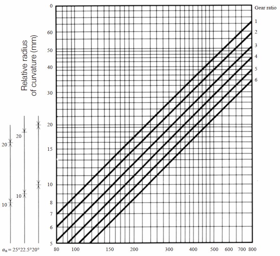
Center distance α (mm)
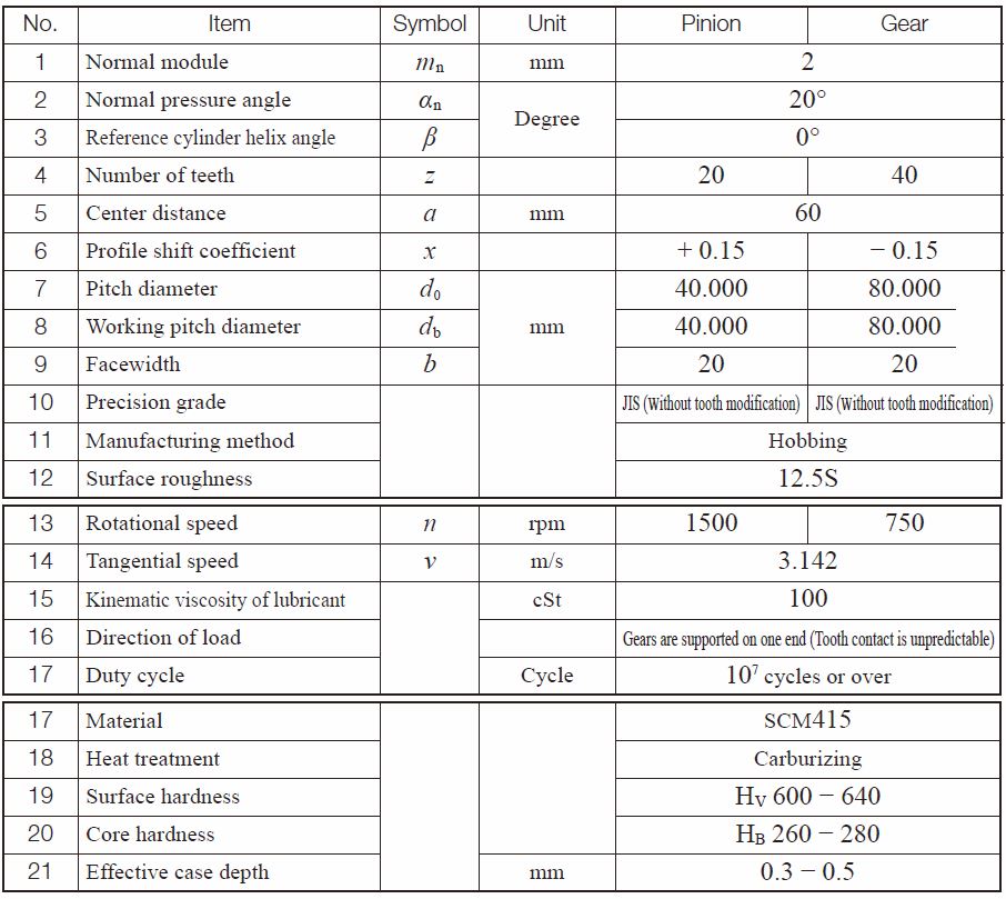
(4) Example of Calculation
Spur gear design details
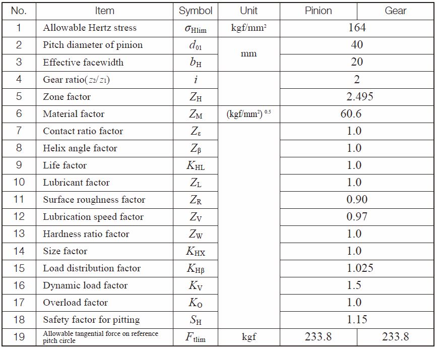
Surface durability factors calculation of spur gear
Related links / 相关链接 :
齿轮的强度
Strength and Durability of Gears – A page of The ABC’s of Gears / Basic Guide – B