


This information is valid for bevel gears which are used for power transmission in general industrial machines. The applicable ranges are:
Transverse module / m / 1.5-25mm
Pitch diameter / d0 / 1600mm or less (Straight bevel gear), 1000mm or less (Spiral bevel gear)
Tangential speed / v / 25m/s or less
Rotational speed / n / 3600rpm or less
(1) Basic Conversion Formulas
Equations (10.27), (10.28) and (10.29) in 1.3 “Bending strength of bevel gears” shall apply.
(2) Surface Durability Equations
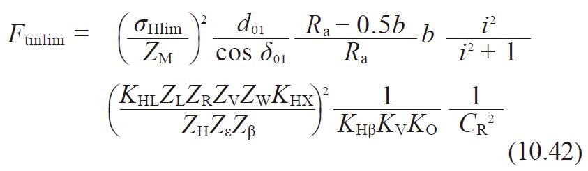
In order to obtain a proper surface durability, the transmitted tangential force at the central pitch circle, Ftm, should not exceed the allowable tangential force at the central pitch circle, Ftmlim, based on the allowable Hertz stress σHlim.
![]()
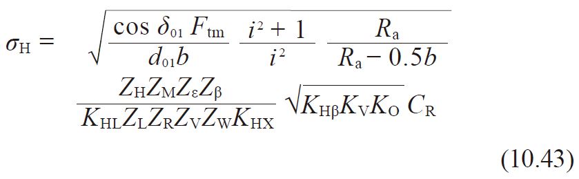
Alternately, the Hertz stress, σH, which is derived from the transmitted tangential force at the central pitch circle should not exceed the allowable Hertz stress, σHlim.
![]()
The allowable tangential force at the central pitch circle, Ftmlim (kgf), can be calculated from Equation (10.42).
The Hertz stress, σH (kgf/mm2) , is calculated from Equation (10.43).
(3) Determinaion of Factors
(3)-1 Facewidth, b
This term is defined as the facewidth on the pitch cone.For a meshed pair, the narrower gear’s b is to be used.
(3)-2 Zone Factor, ZH
The zone factor, ZH, is defined as:
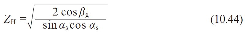
where βm:Mean spiral angle
αn :Normal reference pressure angle
αs :Central transverse pressure angle = tan-1 (tan αn/cos βm)
βg = tan-1 (tan βm cos αs)
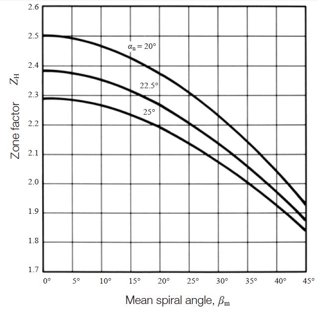
If the normal reference pressure angle, αn, is 20 degree, 22.5 degree or 25 degree, the zone factor, ZH, can be obtained from Figure 10.10.
Fig. 10.10 Zone factor, ZH
(3)-3 Material Factor, ZM
The material factor, ZM, can be obtainable from Table 10.9 in 1.2 “Surface durability of spur gear and helical gear“.
(3)-4 Contact Ratio Factor, Z
The contact ratio factor, Zε, is calculated from the equations below.
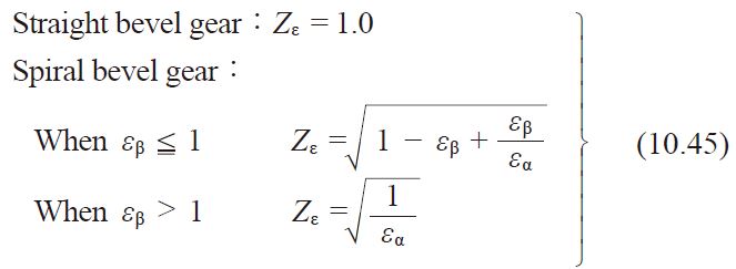
Where
εα :Transverse contact ratio
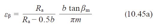
εß :Overlap ratio
(3)-5 Spiral Angle Factor, Zß
Since it is difficult to prescribe the spiral angle factor, Zß, because little is known about this factor, 1.0 is usually used.
Zß = 1.0 (10.46)
(3)-6 Life Factor, KHL
The life factor for surface durability, KHL, is obtainable from Table 10.10 in 1.2 “Surface durability of spur and helical gear”.
(3)-7 Lubricant Factor, ZL
The lubricant factor, ZL, is found in Figure 10.3. See page 673.
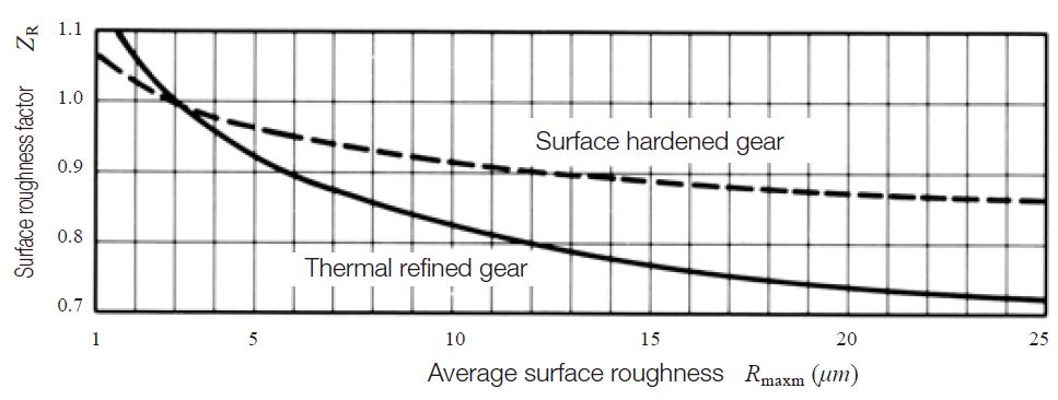
(3)-8 Surface Roughness Factor, ZR
The surface roughness factor, ZR, is obtainable from Figure 10.11 on the basis of average roughness, Rmaxm (μm). The average surface roughness, Rmaxm, is calculated by Equation (10.47) from surface roughness of the pinion and gear ( Rmax1 and Rmax2), and a (mm).
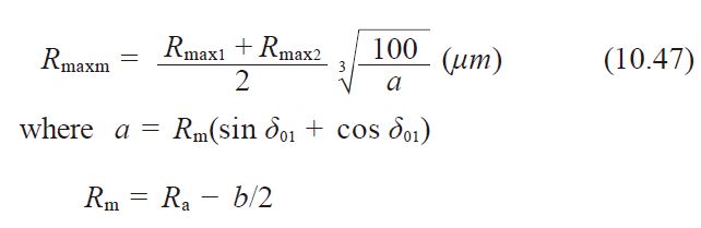
Fig. 10.11 Surface roughness factor,ZR
(3)-9 Lubrication speed factor, ZV
The lubrication speed factor, ZV, is obtained from Figure 10.5. See page 673.
(3)-10 Hardness ratio factor, ZW
The hardness ratio factor, ZW, applies only to the gear that is in mesh with a pinion which is quenched and ground, and can be obtained from Equation (10.48) .
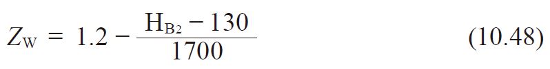
Where HB2:Brinell hardness of the tooth flank of the gear
should be 130 ≦ HB2 ≦ 470
If the gear’s hardness is outside of this range, ZW is assumed to be unity.
ZW = 1.0 (10.49)
(3)-11 Size Factor, KHX
The size factor, KHX, is assumed to be unity because, often, little is known about this factor.
KHX = 1.0 (10.50)
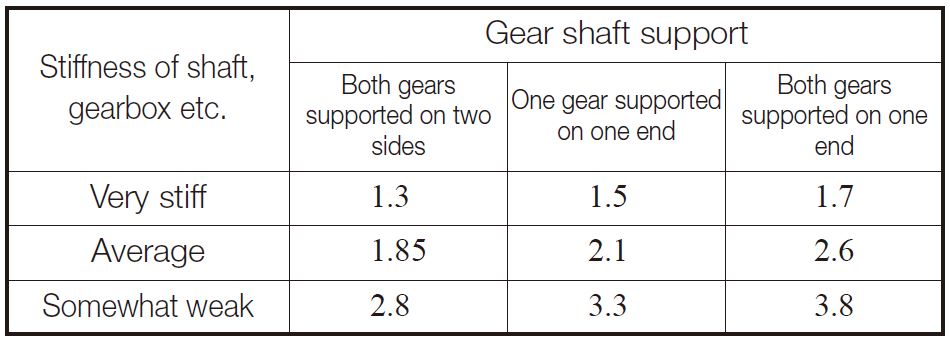
(3)-12 Longitudinal Load Distribution Factor, KHß
The longitudinal load distribution factors are listed in Tables 10.25 and 10.26. If the gear and pinion are unhardened the factors are to be reduced to 90% of the values in the table.
Table 10.25 Longitudinal load distribution factor for spiral bevel gears (zerol bevel gears included), and straight bevel gears with crowning ,KHβ
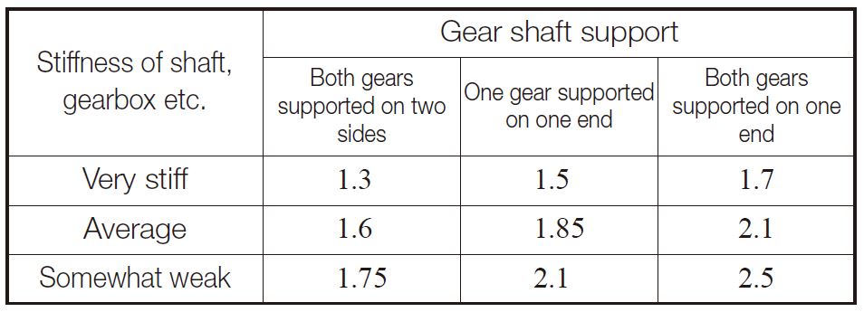
Table 10.26 Longitudinal load distribution factor for straight bevel gear without crowning ,KHβ
(3)-13 Dynamic Load Factor, KV
The dynamic load factor, KV, can be obtained from Table 10.24. See page 683.
(3)-14 Overload Factor, KO
The overload factor, KO, can be computed by Equation (10.12) or found in Table 10.4.
(3)-15 Reliability Factor, CR
The general practice is to assume CR to be at least 1.15.
(3)-16 Allowable Hertz Stress, σHlim
The values of allowable Hertz stress, σHlim, are given in Tables 10.12 through 10.16.
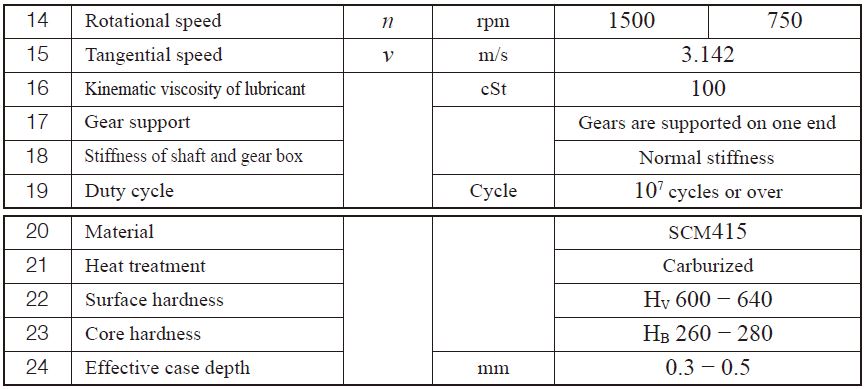
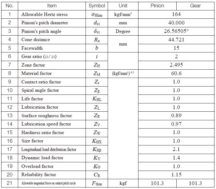
(4) Example of Calculation
Gleason straight bevel gear design details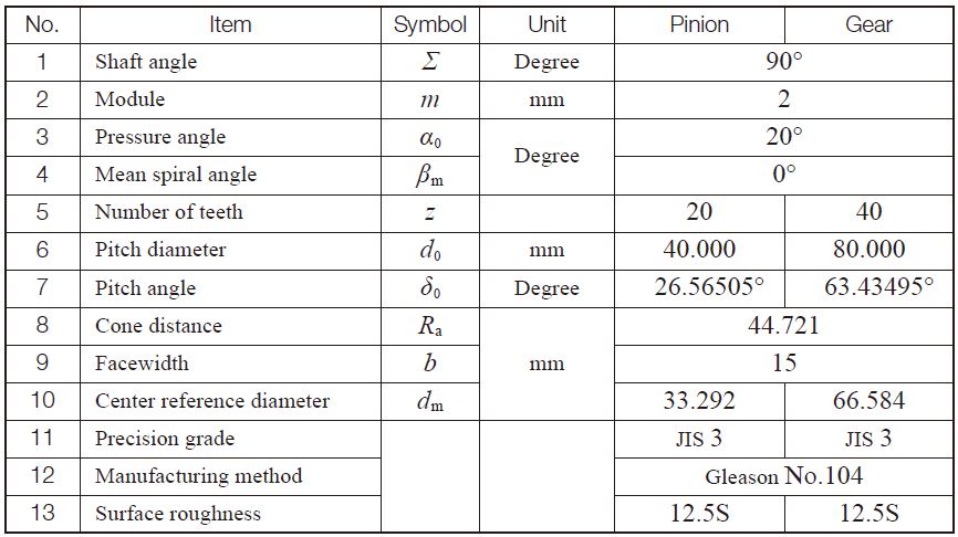
Surface durability factors of Gleason straight bevel gear
Related links / 相关链接 :
齿轮的强度
Strength and Durability of Gears - A page of The ABC’s of Gears / Basic Guide B