


Gears are identified by many types and there are many specific technical words to describe their definition. This section introduces those technical words along with commonly used gears and their features.
1.1 Types of Gears
The most common way to classify gears is by category type and by the orientation of axes.
Gears are classified into 3 categories; parallel axis gears, intersecting axes gears, and nonparallel and nonintersecting axes gears.
Spur gears and helical gears are parallel axes gears.
Bevel gears are intersecting axes gears. Screw or crossed helical, worm gear and hypoid gears belong to the third category. Table 1.1 lists the gear types by axes orientation.
Table 1.1 Types of Gears and Their Categories
- Categories of Gears
Parallel Axes Gears - Types of Gears
Spur Gear
Spur rack
Internal gear
Helical gear
Helical rack
Double helical gear - Efficiency (%)
98.0 – 99.5
- Categories of Gears
Intersecting AxesGears - Types of Gears
Straight bevel gear
Spiral bevel gear
Zerol bevel gear - Efficiency (%)
98.0 – 99.0
- Categories of Gears
Nonparallel and Nonintersecting - Types of Gears
Screw gear (Efficiency 70.0 – 95.0 %)
Worm gear (Efficiency 30.0 – 90.0 %)
Also, included in table 1.1 is the theoretical efficiency range of various gear types. These figures do not include bearing and lubricant losses.
Since meshing of paired parallel axis gears or intersecting axis gears involves simple rolling movements, they produce relatively minimal slippage and their efficiency is high.
Nonparallel and nonintersecting gears, such as screw gears or worm gears, rotate with relative slippage and by power transmission, which tends to produce friction and makes the efficiency lower when compared to other types of gears.
Efficiency of gears is the value obtained when the gears are installed and working accurately. Particularly for bevel gears, it is assumed that the efficiency will decrease if improperly mounted from off-position on the cone-top.
(1) Parallel Axes Gears
1 Spur Gear
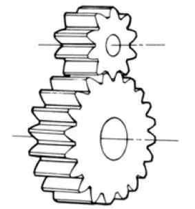
Fig. 1.1 Spur Gear
This is a cylindrical shaped gear, in which the teeth are parallel to the axis. It is the most commonly used gear with a wide range of applications and is the easiest to manufacture.
2 Gear Rack
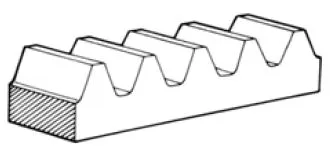
Fig. 1.2 Gear Rack
This is a linear shaped gear which can mesh with a spur gear with any number of teeth. The
gear rack
is a portion of a spur gear with an infinite radius.
3 Internal Gear
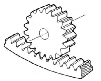
Fig. 1.3 Internal Gear and Spur Gear
This is a cylindrical shaped gear, but with the teeth inside the circular ring. It can mesh with a spur gear. Internal gears are often used in planetary gear systems.
4 Helical Gear
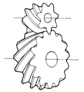
Fig. 1.4 Helical Gear
This is a cylindrical shaped gear with helicoid teeth. Helical gears can bear more load than spur gears, and work more quietly. They are widely used in industry. A disadvantage is the axial
thrust
force caused by the helix form.
5 Helical Rack
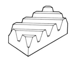
Fig. 1.5 Helical Rack
This is a linear shaped gear that meshes with a helical gear. A Helical Rack can be regarded as a portion of a helical gear with infinite radius.
6 Double Helical Gear
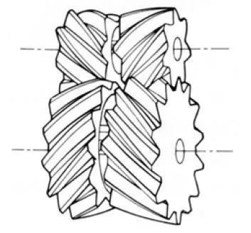
Fig1.6 Double Helical Gear
A gear with both left-hand and right-hand helical teeth. The double helical form balances the inherent thrust forces.
(2) Intersecting Axes
1 Straight Bevel Gear
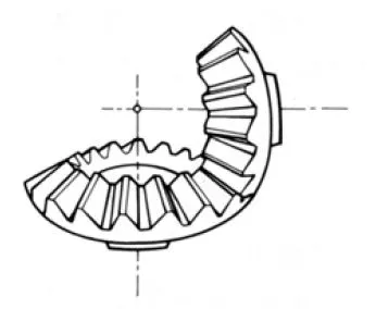
Fig.1.7 Straight Bevel Gear
This is a gear in which the teeth have tapered conical elements that have the same direction as the pitch cone base line (generatrix). The straight bevel gear is both the simplest to produce and the most widely applied in the bevel gear family.
2 Spiral Bevel Gear
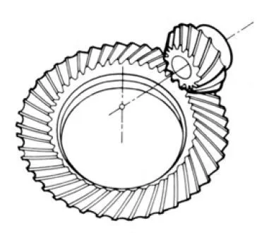
Fig.1.8 Spiral Bevel Gear
This is a bevel gear with a helical angle of spiral teeth. It is much more complex to manufacture, but offers higher strength and less noise.
3 Zerol Bevel Gear
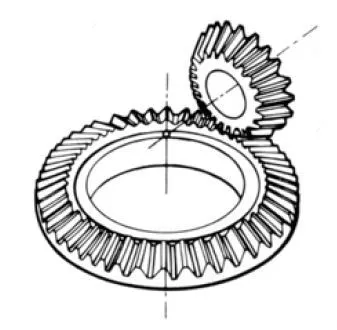
Fig.1.9 Zerol Bevel Gear
This is a special type of spiral bevel gear, where the spiral angle is zero degree. It has the characteristics of both the straight and spiral bevel gears. The forces acting upon the tooth are the same as for a straight bevel gear.
(3) Nonparallel and Nonintersecting Axes Gears
1 Worm Gear Pair
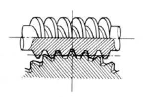
Fig.1.10 Worm Gear pair
Worm gear pair is the name for a meshed worm and worm wheel. An outstanding feature is that it offers a very large gear ratio in a single mesh. It also provides quiet and smooth action. However, transmission efficiency is poor.
2 Screw Gear (Crossed Helical Gear)
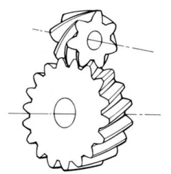
Fig.1.11 Screw Gear
A pair of cylindrical gears used to drive non-parallel and nonintersecting shafts where the teeth of one or both members of the pair are of screw form. Screw gears are used in the combination of screw gear / screw gear, or screw gear / spur gear. Screw gears assure smooth, quiet operation. However, they are not suitable for transmission of high horsepower.
(4) Other Special Gears
1 Face Gear
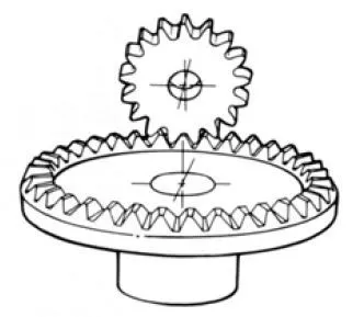
Fig.1.12 Face Gear
A pseudo bevel gear that is limited to 90° intersecting axes. The face gear is a circular disc with a ring of teeth cut in its side face; hence the name Face Gear.
2 Enveloping Gear Pair
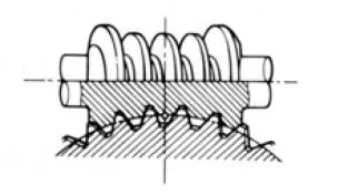
Fig.1.13 Enveloping Gear Pair
This worm set uses a special worm shape that partially envelops the worm gear as viewed in the direction of the worm gear axis. Its big advantage over the standard worm is much higher load capacity. However, the worm gear is very complicated to design and produce.
3 Hypoid Gear
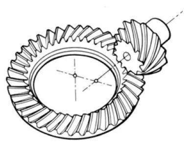
Fig.1.14 Hypoid Gear
This gear is a slight deviation from a bevel gear that originated as a special development for the automobile industry. This permitted the drive to the rear axle to be nonintersecting, and thus allowed the auto body to be lowered. It looks very much like the spiral bevel gear. However, it is complicated to design and is the most difficult to produce on a bevel gear generator.
1.2 Symbols and Terminology
Symbols and technical words used in this catalog are listed in Table 1.2 to Table 1.4. The formerly used JIS B 0121 and JIS B 0102 Standards were revised to JIS B 0121:1999 and JIS B 0102:1999 conforming to the International Standard Organization (ISO) Standard. In accordance with the revision, we have unified the use of words and symbols conforming to the ISO standard.
Table 1.2 Linear and Circular Dimensions
Terms and Symbols
- Centre distance

- Reference pitch

- Transverse pitch

- Normal pitch

- Axial pitch

- Base pitch

- Transverse base pitch

- Normal base pitch

- Tooth depth

- Addendum

- Dedendum

- Chordal height

- Constant chord height

- Working depth

- Tooth thickness

- Normal tooth thickness

- Transverse tooth thickness

- Crest width

- Base thickness

- Chordal tooth thickness

- Constant chord

- Span measurement over k teeth

- Tooth space

- Tip and root clearance

- Circumferential backlash

- Normal backlash

- Radial backlash

- Axial backlash (Radial play) NOTE 1

- Angular backlash

- Facewidth

- Effective facewidth

- Lead

- Length of path of contact

- Length of approach path

- Length of recess path

- Overlap length

- Reference diameter

- Pitch diameter

- Tip diameter

- Base diameter

- Root diameter

- Center reference diameter

- Inner tip diameter

- Reference radius

- Pitch radius

- Tip radius

- Base radius

- Root radius

- Radius of curvature of tooth profile

- Cone distance

- Back cone distance

* NOTE 1.
“Axial backlash” is not a word defined by JIS.
Table 1.3 Angular Dimensions
Terms and Symbols
- Reference
pressure angle

- Working pressure angle

- Cutter pressure angle

- Transverse pressure angle

- Normal pressure angle

- Axial pressure angle

- Transverse working pressure angle

- Tip pressure angle

- Normal working pressure angle
- Reference cylinder helix angle

- Pitch cylinder helix angle

- Mean spiral angle NOTE 2

- Tip cylinder helix angle

- Base cylinder helix angle

- Reference cylinder lead angle

- Pitch cylinder lead angle

- Tip cylinder lead angle

- Base cylinder lead angle

- Shaft angle

- Reference cone angle

- Pitch angle NOTE 3

- Tip angle NOTE 4

- Root angle NOTE 5

- Addendum angle

- Dedendum angle

- Transverse angle of transmission

- Overlap angle

- Total angle of transmission

- Tooth thickness half angle

- Tip tooth thickness half angle

- Spacewidth half angle

- Angular pitch of crown gear

- Involute function (Involute
α )

NOTE 2. The spiral angle of spiral bevel gears was defined as the helix angle by JIS B 0102
NOTE 3. This must be Pitch Angle, according to JIS B 0102.
NOTE 4. This must be Tip Angle, according to JIS B 0102.
NOTE 5. This must be Root Angle, according to JIS B 0102.
Table 1.4 Others
Terms and Symbols
- Number of teeth

- Equivalent number of teeth

- Number of threads, or number of teeth in pinion

- Gear ratio

- Transmission ratio

- Module

- Transverse module

- Normal module

- Axial module

- Diametral pitch

-
Transverse contact ratio

- Overlap ratio

- Total contact ratio

- Angular speed

- Tangential speed

- Rotational speed

- Profile shift coefficient

- Normal profile shift coefficient

- Transverse profile shift coefficient

- Center distance modification coefficient

- Tangential force (Circumference)

- Axial force (Thrust)

- Radial force

- Pin diameter

- Ideal pin diameter

- Measurement over rollers (pin)

- Pressure angle at pin center

- Coefficient of friction

- Circular thickness factor

- Single pitch deviation

- Pitch deviation

- Total cumulative pitch deviation

- Total profile deviation

- Runout

- Total helix deviation

A numerical subscript is used to distinguish “pinion” from “gear” (Example z1 and z2), “worm” from “worm wheel”, “drive gear” from “driven gear”, and so forth. (To find an example, see next page Fig. 2.1).
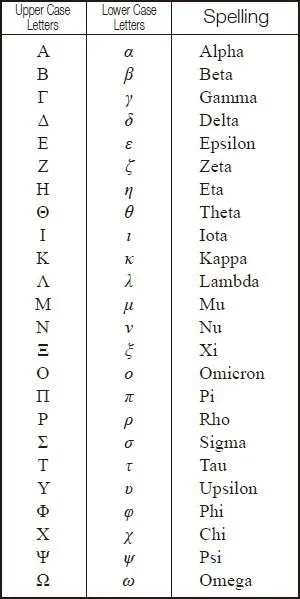
Table 1.5 indicates the Greek alphabet, the international phonetic alphabet.
Table 1.5 The Greek alphabet
Related links :
齿轮的种类及术语
Know about rotational directions and numbers of rotation of gears
Gear Types and Characteristics
– A page of The ABCS of Gears – B
Basic Gear Terminology and Calculation
– A page of The ABCS of Gears – B
Types of Gears
– A page of Introduction to Gears
Characteristics of Gears
– A page of Introduction to Gears
Gear Terminology
– A page of Introduction to Gears
Gear Nomenclature