


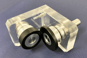
Clean, Quiet, and Safe Motion — Powered by Non-Contact Technology
- No particle generation caused by tooth surface wear
- Lubrication-free operation
- Barrier transmission enables seal-less structures
- Low noise and vibration through non-contact power transmission
- Easier assembly with high angular and eccentric misalignment tolerance
- Magnetic slip under overload helps improve safety
This section introduces planetary gear systems, hypocycloid mechanisms, and constrained gear systems, which are special gear systems which offer features such as compact size and high reduction ratio.
17.1 Planetary Gear System
The basic form of a planetary gear system is shown in Figure 17.1. It consists of a sun gear A, planet gears B, internal gear C and carrier D.
Fig.17.1 An example of a planetary gear system
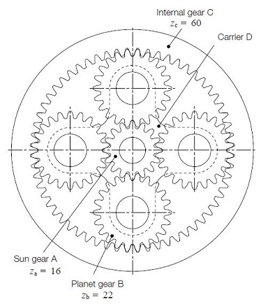
The input and output axes of a planetary gear system are on a same line. Usually, it uses two or more planet gears to balance the load evenly. It is compact in space, but complex in structure. Planetary gear systems need a high-quality manufacturing process. The load division between planet gears, the interference of the internal gear, the balance and vibration of the rotating carrier, and the hazard of jamming, etc. are inherent problems to be solved.
Figure 17.1 is a so called 2K-H type planetary gear system. The sun gear, internal gear, and the carrier have a common axis.
(1) Relationship Among the Gears in a Planetary Gear System
In order to determine the relationship among the numbers of teeth of the sun gear(za), the planet gears B(zb) and the internal gear C(zc) and the number of planet gears N in the system, these parameters must satisfy the following three conditions :
Condition No.1
zc = za + 2 zb (17.1)
This is the condition necessary for the center distances of the gears to match. Since the equation is true only for the standard gear system, it is possible to vary the numbers of teeth by using profile shifted gear designs.
To use profile shifted gears, it is necessary to match the center distance between the sun A and planet B gears, a1, and the center distance between the planet B and internal C gears, α2.
α1 = α2 (17.2)
Condition No.2
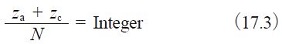
This is the condition necessary for placing planet gears evenly spaced around the sun gear. If an uneven placement of planet gears is desired, then Equation (17.4) must be satisfied.
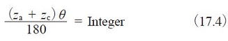
Where θ:half the angle between adjacent planet gears (°)
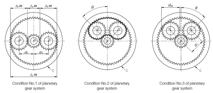
Fig.17.2 Conditions for selecting gears
Condition No.3
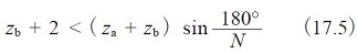
Satisfying this condition insures that adjacent planet gears can operate without interfering with each other. This is the condition that must be met for standard gear design with equal placement of planet gears. For other conditions, the system must satisfy the relationship :

Where:
dab:Tip diameter of the planet gears
α1:Center distance between the sun and planet gears
Besides the above three basic conditions, there can be an interference problem between the internal gear C and the planet gears B. See Section 4.2 Internal Gears (Page 611 to 613).
(2) Transmission Ratio of Planetary Gear System
In a planetary gear system, the transmission ratio and the direction of rotation would be changed according to which member is fixed. Figure 17.3 contain three typical types of planetary gear mechanisms,
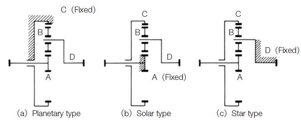
Fig.17.3 Planetary gear mechanism
(a) Planetary Type
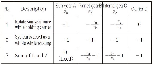
In this type, the internal gear is fixed. The input is the sun gear and the output is carrier D. The transmission ratio is calculated as in Table 17.1.
Table17.1 Equations of transmission ratio for a planetary type
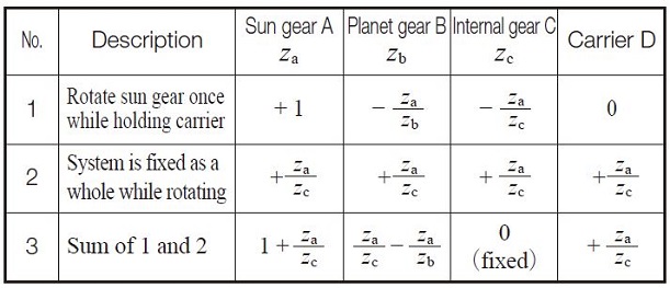
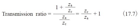
Note that the direction of rotation of input and output axes are the same. Example: za = 16, zb = 16, zc = 48, then transmission ratio = 4.
(b) Solar Type
In this type, the sun gear is fixed. The internal gear C is the input, and carrier D axis is the output. The speed ratio is calculated as in Table 17.2.
Table 17.2 Equations of transmission ratio for a solar type
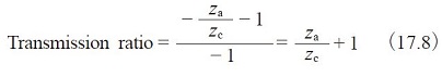
Note that the directions of rotation of input and output axes are the same. Example: za = 16, zb = 16, zc = 48, then the transmission ratio = 1.33333
(c) Star Type
This is the type in which Carrier D is fixed. The planet gears B rotate only on fixed axes. In a strict definition, this train loses the features of a planetary system and it becomes an ordinary gear train. The sun gear is an input axis and the internal gear is the output. The transmission ratio is :
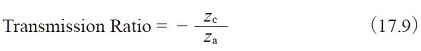
Referring to Figure 2.3(c), the planet gears are merely idlers.
Input and output axes have opposite rotations.
Example: za = 16, zb = 16, zc = 48,
then transmission ratio = -3 .
17.2 Hypocycloid Mechanism
In the meshing of an internal gear and an external gear, if the difference in numbers of teeth of two gears is quite small, a profile shifted gear could prevent the interference. Table 17.3 is an example of how to prevent interference under the conditions of z2 = 50 and the difference of numbers of teeth of two gears ranges from 1 to 8.
Table 17.3 The meshing of internal and external gears of small difference of numbers of teeth
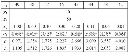
All combinations above will not cause involute interference or trochoid interference, but trimming interference is still present.
In order to assemble successfully, the external gear should be assembled by inserting it in the axial direction. A profile shifted internal gear and external gear, in which the difference of numbers of teeth is small, belong to the field of hypocyclic mechanisms, which can produce a large reduction ratio in single step, such as 1/100.
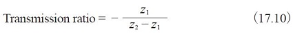
In Figure 17.4 the gear train has a difference of numbers of teeth of only 1; z1 = 30 and z2 = 31. This results in a transmission ratio of 30.
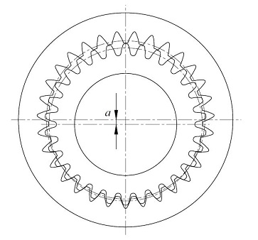
Fig.17.4 The meshing of internal gear and external gear in which the numbers of teeth difference is 1
17.3 Constrained Gear System
A planetary gear system which has four gears is an example of a constrained gear system. It is a closed loop system in which the power is transmitted from the driving gear through other gears and eventually to the driven gear. A closed loop gear system will not work if the gears do not meet specific conditions.
Let z1, z2 and z3 be the numbers of gear teeth, as in Figure 17.5 Meshing cannot function if the length of the heavy line (belt) does not divide evenly by pitch. Equation(17.11) defines this condition.
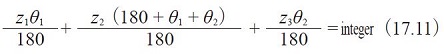
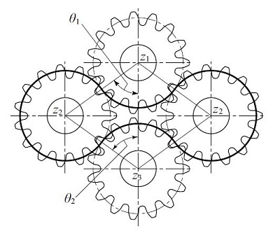
Fig.17.5 Constrained gear system
Figure 17.6 shows a constrained gear system in which a gear rack is meshed. The heavy line in Figure 17.6 corresponds to the belt in Figure 17.5. If the length of the belt cannot be evenly divided by pitch then the system does not work. It is described by Equation(17.12).
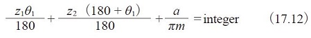
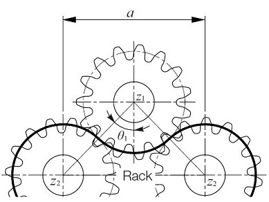
Fig.17.6 Constrained gear system containing a rack
Related links :
齿轮机构
Spur Gears
Planetary gear mechanism