


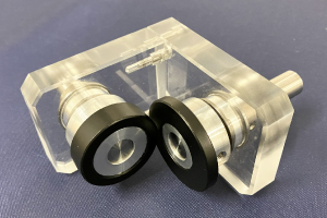
Clean, Quiet, and Safe Motion — Powered by Non-Contact Technology
- No particle generation from tooth surface wear
- Operates without the need for Lubrication
- Barrier transmission allows for seal-less designs
- Low noise and vibration due to non-contact power transmission
- Easier assembly with high angular and eccentric misalignment tolerance
- Magnetic slip under overload enhances safety conditions
See Applications & Benefits (PDF)
Gear dimensions are determined in accordance with their specifications, such as Module (m), Number of teeth (z), Pressureangle (α), and Profile shift coefficient (x). This section introduces the dimension calculations for spur gears, helical gears, gear rack, bevel gears, screw gears, and worm gear pairs. Calculations of external dimensions (eg. Tip diameter) are necessary for processing the gear blanks. Tooth dimensionssuch as root diameter or tooth depth are considered when gear cutting.
4.1 Spur Gears
Spur Gears are the simplest type of gear. The calculations for spur gears are also simple and they are used as the basisfor the calculations for other types of gears. This section introduces calculation methods of standard spur gears, profileshifted spur gears, and linear racks. The standard spur gear is a non-profile-shifted spur gear.
(1) Standard Spur Gear
Figure 4.1 shows the meshing of standard spur gears. The meshing of standard spur gears means the reference circlesof two gears contact and roll with each other. The calculation formulas are in Table 4.1.
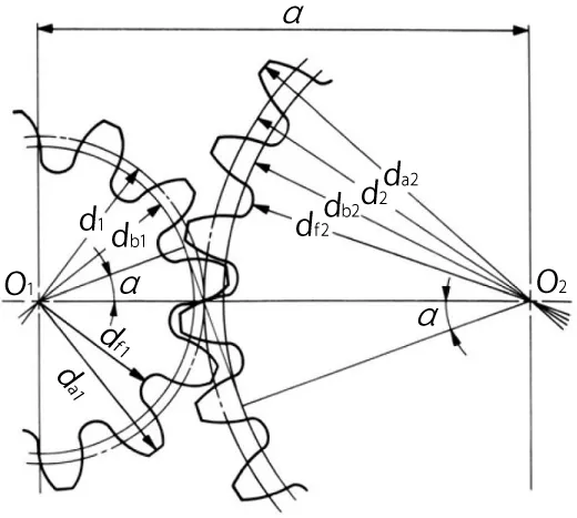
Fig. 4.1 The Meshing of Standard Spur Gears
( α=20°, z1=12, z2=24, x1=x2=0 )
| No. | Item | Symbol | Formula | Example | |
| Pinion (1) | Gear (2) | ||||
| 1 | Module | m | Set Value | 3 | |
| 2 | Reference Pressure Angle | α | 20 deg | ||
| 3 | Number of Teeth | z | 12 | 24 | |
| 4 | Center Distance | a | (z1 + z2) m / 2NOTE1 | 54.000 | |
| 5 | Reference Diameter | d | zm | 36.000 | 72.000 |
| 6 | Base Diameter | db | d cos α | 33.829 | 67.658 |
| 7 | Addendum | ha | 1.00m | 3.000 | 3.000 |
| 8 | Tooth Depth | h | 2.25m | 6.750 | 6.750 |
| 9 | Tip Diameter | da | d + 2m | 42.000 | 78.000 |
| 10 | Root Diameter | df | d – 2.5m | 28.500 | 64.500 |
NOTE 1 : The subscripts 1 and 2 of z1 and z2 denote pinion and gear
All calculated values in Table 4.1 are based upon given module m and number of teeth (z1 and z2). If instead, the modulem, center distance a and speed ratio i are given, then the number of teeth, z1 and z2, would be calculated using theformulas as shown in Table 4.2.
Table 4.2 The Calculations for Number of Teeth| No. | Item | Symbol | Formula | Example | ||
| Pinion (1) | Gear (2) | |||||
| 1 | Module | m | Set Value | 3 | ||
| 2 | Center Distance | a | 54.000 | |||
| 3 | Speed Ratio | i | 1.25 | |||
| 4 | Sum of No. of Teeth | z1 + z2 | 2a / m | 36 | ||
| 5 | Number of Teeth | z | z1 + z2 / i + 1 | i (z1 + z2) / i + 1 | 16 | 20 |
Note, that the number of teeth will probably not be integer values when using the formulas in Table 4.2. In this case,it will be necessary to resort to profile shifting or to employ helical gears to obtain as near a transmission ratioas possible.
(2) Profile Shifted Spur Gear
Figure 4.2 shows the meshing of a pair of profile shifted gears. The key items in profile shifted gears are the operating(working) pitch diameters (dw) and the working (operating) pressure angle (αw). These values are obtainable from themodified center distance and the following formulas :
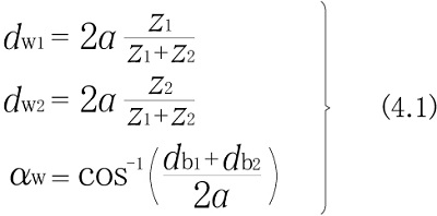
In the meshing of profile shifted gears, it is the operating pitch circle that is in contact and roll on each other thatportrays gear action. Table 4.3 presents the calculations where the profile shift coefficient has been set at x1 and x2 at the beginning. This calculation is based on the idea that the amount of the tip and root clearance should be 0.25m.
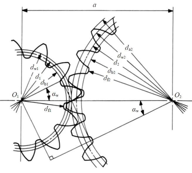
Fig. 4.2 The Meshing of Profile Shifted Gears
( α=20°, z1=12, z2=24, x1=+0.6, x2=+0.36 )
| No. | Item | Symbol | Formula | Example | |
| Pinion (1) | Gear (2) | ||||
| 1 | Module | m | Set Value | 3 | |
| 2 | Reference Pressure Angle | α | 20 deg | ||
| 3 | Number of Teeth | z | 12 | 24 | |
| 4 | Profile Shift Coefficient | X | 0.6 | 0.36 | |
| 5 | Involute αw | inv αw | 2 tan α (x1 + x2 / z1 + z2) + inv α | 0.034316 | |
| 6 | Working Pressure Angle | αw | Find from Involute Function Table | 26.0886 deg | |
| 7 | Center Distance Modification Coefficient | y | z1 + z2 / 2 (cos α / cos αw - 1) | 0.83329 | |
| 8 | Center Distance | a | (z1 + z2 / 2 + y) m | 56.4999 | |
| 9 | Reference Diameter | d | zm | 36.000 | 72.000 |
| 10 | Base Diameter | db | d cos α | 33.8289 | 67.6579 |
| 11 | Working Pitch Diameter | dw | db / cos αw | 37.667 | 75.333 |
| 12 | Addendum | ha1 ha2 | ( 1 + y – x2 ) m ( 1 + y – x1 ) m | 4.420 | 3.700 |
| 13 | Tooth Depth | h | {2.25 + y – ( x1 + x2 )}m | 6.370 | |
| 14 | Tip Diameter | da | d + 2ha | 44.840 | 79.400 |
| 15 | Root Diameter | df | da – 2h | 32.100 | 66.660 |
A standard spur gear is, according to Table 4.3, a profile shifted gear with 0 coefficient of shift; that is , x1=x2=0.
Table 4.4 is the inverse formula of items from 4 to 8 of Table 4.3.
Table 4.4 The Calculations for Profile Shifted Spur Gears (2)| No. | Item | Symbol | Formula | Example | |
| Pinion (1) | Gear (2) | ||||
| 1 | Center Distance | a | Set Value | 56.4999 | |
| 2 | Center Distance Modification Coefficient | y | 0.8333 | ||
| 3 | Working Pressure Angle | αw | 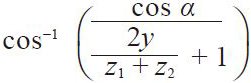 | 26.0886 deg | |
| 4 | Sum of Profile Shift Coefficient | x1 + x2 | 0.9600 | ||
| 5 | Profile Shift Coefficient | x | – | 0.6000 | 0.3600 |
There are several theories concerning how to distribute the sum of profile shift coefficient (x1 + x2) into pinion (x1)and gear (x2) separately. BSS (British) and DIN (German) standards are the most often used. In the example above, the12 tooth pinion was given sufficient correction to preventundercut, and the residual profile shift was given to the mating gear.
(3) Rack and Spur Gear
Table 4.5 presents the method for calculating the mesh of a rack and spur gear.
Figure 4.3 (1) shows the the meshing of standard gear and a rack. In this mesh, the reference circle of the gear touchesthe pitch line of the rack.
Figure 4.3 (2) shows a profile shifted spur gear, with positive correction xm, meshed with a rack. The spur gear hasa larger pitch radius than standard, by the amount xm. Also, the pitch line of the rack has shifted outward by the amount xm.
Table 4.5 presents the calculation of a meshed profile shifted spur gear and rack. If the profile shift coefficient x1 is 0, then it is the case of a standard gear meshed with the rack.
| No. | Item | Symbol | Formula | Example | |
| Spur gear | Rack | ||||
| 1 | Module | m | Set Value | 3 | |
| 2 | Reference pressure angle | a | 20 deg | ||
| 3 | Number of teeth | z | 12 | – | |
| 4 | Profile shift coefficient | x | 0.6 | ||
| 5 | Height of pitch line | H | – | 32.000 | |
| 6 | Working pressure angle | αw | 20 deg | ||
| 7 | Mounting distance | a |  | 51.800 | |
| 8 | Reference diameter | d | zm | 36.000 | – |
| 9 | Base diameter | db | d cos α | 33.829 | |
| 10 | Working pitch diameter | dw | 36.000 | ||
| 11 | Addendum | ha | m ( 1 + x ) | 4.800 | 3.000 |
| 12 | Tooth depth | h | 2.25m | 6.750 | |
| 13 | Tip diameter | da | d + 2ha | 45.600 | – |
| 14 | Root diameter | df | da – 2h | 32.100 | |
One rotation of the spur gear will displace the rack l one circumferential length of the gear’s reference circle,per the formula :![]()
The rack displacement, l, is not changed in any way by the profile shifting. Equation (4.2) remains applicable for anyamount of profile shift.
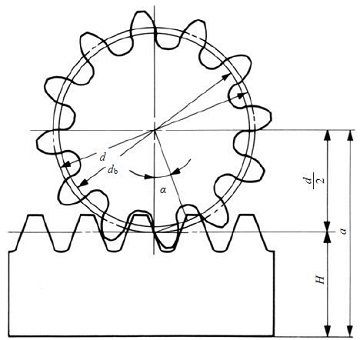
Fig. 4.3 (1) The meshing of standard spur gear and rack
( α=20°, z1=12, x1=0 )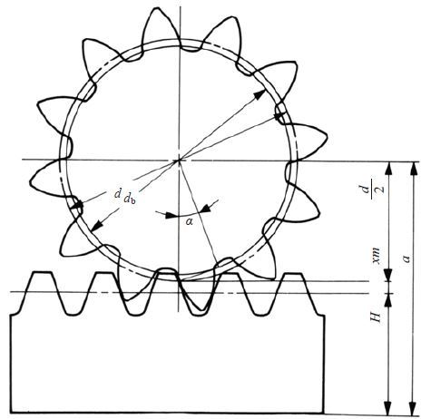
Fig. 4.3 (2) The meshing of profile shifted spur gear and rack
( α=20°, z1=12, x1=+ 0.6 )
4.2 Internal Gears
Internal Gears are composed of a cylindrical shaped gear having teeth inside a circular ring. Gear teeth of the internalgear mesh with the teeth space of a spur gear. Spur gears have a convex shaped tooth profile and internal gears havereentrant shaped tooth profile; this characteristic is opposite of Internal gears. Here are the calculations for thedimensions of internal gears and their interference.
(1) Internal Gear Calculations
Figure 4.4 presents the mesh of an internal gear and external gear. Of vital importance is the working pitch diameters(dw) and working pressure angle (αw). They can be derived from center distance (a) and Equations (4.3).
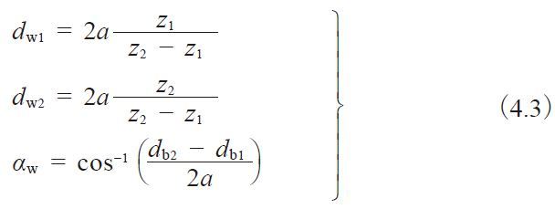
Table 4.6 shows the calculation steps. It will become a standard gear calculation if x1=x2=0.
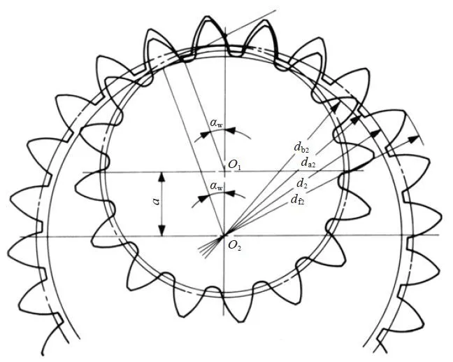
Fig.4.4 The meshing of internal gear and external gear
( α=20°, z1=16, z2=24, x1=x2=+0.5 )
Table 4.6 The calculations of a profile shifted internal gear and external gear (1)
| No. | Item | Symbol | Formula | Example | |
| External gear (1) | Internal gear (2) | ||||
| 1 | Module | m | Set Value | 3 | |
| 2 | Reference pressure angle | α | 20 deg | ||
| 3 | Number of teeth | z | 16 | 24 | |
| 4 | Profile shift coefficient | x | 0 | + 0.516 | |
| 5 | Involute function αw | inv αw | 0.061857 | ||
| 6 | Working pressure angle | αw | Find from involute Function Table | 31.321258 deg | |
| 7 | Center distance modification coefficient | y | 0.4000 | ||
| 8 | Center distance | a | 13.2 | ||
| 9 | Reference diameter | d | zm | 48.000 | 72.000 |
| 10 | Base diameter | db | d cos α | 45.105 | 67.658 |
| 11 | Working pitch diameter | dw | 52.7998 | 79.1997 | |
| 12 | Addendum | ha1 ha2 | ( 1 + x1 ) m ( 1 – x2 ) m | 3.000 | 1.452 |
| 13 | Tooth depth | h | 2.25m | 6.75 | |
| 14 | Tip diameter | da1 da2 | d1 + 2ha1 d2 – 2ha2 | 54.000 | 69.096 |
| 15 | Root diameter | df1 df2 | da1 + 2h da2+ 2h | 40.500 | 82.596 |
If the center distance (a) is given, x1 and x2 would be obtained from the inverse calculation from item 4 to item 8 of Table 4.6. These inverse formulas are in Table 4.7.
Table 4.7 The calculations of profile shifted internal gear and external gear (2)
| No. | Item | Symbol | Formula | Example | |
| External gear (1) | Internal gear (2) | ||||
| 1 | Center distance | a | Set Value | 13.1683 | |
| 2 | Center distance modification coefficient | y | 0.38943 | ||
| 3 | Working pressure angle | αw | 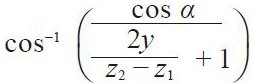 | 31.0937 deg | |
| 4 | Difference of profile shift coefficients | X2 – X1 | 0.5 | ||
| 5 | Profile shift coefficient | X | – | 0 | 0.5 |
Pinion cutters are often used in cutting internal gears and external gears. The actual value of tooth depth and rootdiameter, after cutting, will be slightly different from the calculation. That is because the cutter has a profile shiftcoefficient. In order to get a correct tooth profile, the profile shift coefficient of cutter should be taken into consideration.
(2) Interference In Internal Gears
Three different types of interference can occur with internal gears: (a) Involute Interference, (b) Trochoid Interference,and (c) Trimming Interference.
(a) Involute Interference
This occurs between the dedendum of the external gear and the addendum of the internal gear. It is prevalent when thenumber of teeth of the external gear is small. Involute interference can be avoided by the conditions cited below :
![]()
Where αa2 is the pressure angle at a tip of the internal gear tooth.
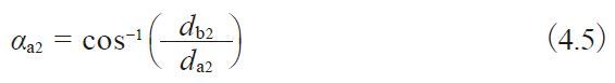
αw:working pressure angle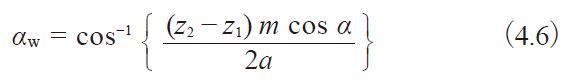
Equation (4.5) is true only if the tip diameter of the internal gear is bigger than the base circle :
![]()
For a standard internal gear, where α=20° , Equation (4.7) is valid only if the number of teeth is z2 > 34.
(b) Trochoid Interference
This refers to an interference occurring at the addendum of the external gear and the dedendum of the internal gearduring recess tooth action. It tends to happen when the difference between the numbers of teeth of the two gears issmall. Equation (4.8) presents the condition for avoiding trochoidal interference.
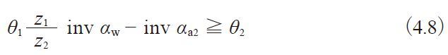
Here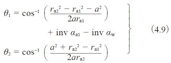
where αa1 is the pressure angle of the spur gear tooth tip: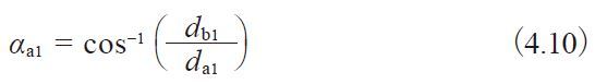
In the meshing of an external gear and a standard internal gear α=20° , trochoid interference is avoided if the differenceof the number of teeth, z2 – z1, is larger than 9.
(c) Trimming Interference
This occurs in the radial direction in that it prevents pulling the gears apart. Thus, the mesh must be assembled bysliding the gears together with an axial motion. It tends to happen when the numbers of teeth of the two gears are veryclose. Equation (4.11) indicates how to prevent this type of interference.
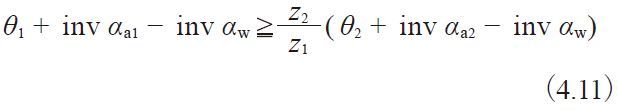
Here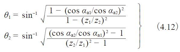
This type of interference can occur in the process of cutting an internal gear with a pinion cutter. Should that happen,there is danger of breaking the tooling. Table 4.8 (1) shows the limit for the pinion cutter to prevent trimming interferencewhen cutting a standard internal gear, with pressure angle α0=20°, and no profile shift, i.e., x0=0.
α0=20°, x0=x2=0
| z0 | 15 | 16 | 17 | 18 | 19 | 20 | 21 | 22 | 24 | 25 | 27 |
| z2 | 34 | 34 | 35 | 36 | 37 | 38 | 39 | 40 | 42 | 43 | 45 |
| z0 | 28 | 30 | 31 | 32 | 33 | 34 | 35 | 38 | 40 | 42 |
| z2 | 46 | 48 | 49 | 50 | 51 | 52 | 53 | 56 | 58 | 60 |
| z0 | 44 | 48 | 50 | 56 | 60 | 64 | 66 | 80 | 96 | 100 |
| z2 | 62 | 66 | 68 | 74 | 78 | 82 | 84 | 98 | 114 | 118 |
There will be an involute interference between the internal gear and the pinion cutter if the number of teeth of thepinion cutter ranges from 15 to 22 (z0=15 to 22). Table 4.8(2) shows the limit for a profile shifted pinion cutterto prevent trimming interference while cutting a standard internal gear. The correction (x0) is the magnitude of shiftwhich was assumed to be: x0=0.0075z0 + 0.05.
Table 4.8 (2) The limit to prevent an internal gear from trimming interference
| z0 | 15 | 16 | 17 | 18 | 19 | 20 | 21 | 22 | 24 | 25 | 27 | 28 | 30 | 31 | 32 | 33 | 34 | 35 | 38 | 40 | 42 | 44 | 48 | 50 | 56 | 60 | 64 | 66 | 80 | 96 | 100 |
| x0 | 0.1625 | 0.17 | 0.1775 | 0.185 | 0.1925 | 0.2 | 0.2075 | 0.215 | 0.23 | 0.2375 | 0.2525 | 0.26 | 0.275 | 0.2825 | 0.29 | 0.2975 | 0.305 | 0.3125 | 0.335 | 0.35 | 0.365 | 0.38 | 0.41 | 0.425 | 0.47 | 0.5 | 0.53 | 0.545 | 0.65 | 0.77 | 0.8 |
| z2 | 36 | 38 | 39 | 40 | 41 | 42 | 43 | 45 | 47 | 48 | 50 | 52 | 54 | 55 | 56 | 58 | 59 | 60 | 64 | 66 | 68 | 71 | 76 | 78 | 86 | 90 | 95 | 98 | 115 | 136 | 141 |
There will be an involute interference between the internal gear and the pinion cutter if the number of teeth of thepinion cutter ranges from 15 to 19 (z0=15 to 19).
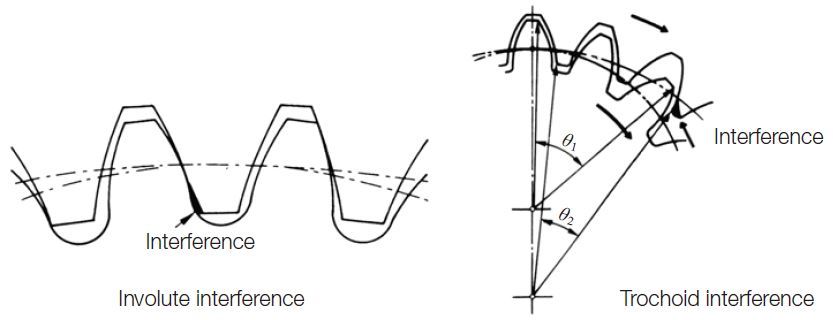
Fig.4.5 Involute interference and trochoid interference
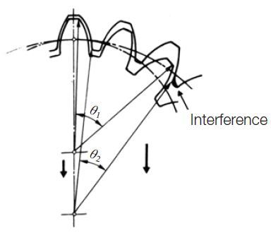
Fig.4.6 Trimming interference
4.3 Helical Gears
A helical gear such as shown in Figure 4.7 is a cylindrical gear in which the teeth flank are helicoid. The helix anglein reference cylinder is β, and the displacement of one rotation is the lead, pz.
The tooth profile of a helical gear is an involute curve from an axial view, or in the plane perpendicular to the axis. The helical gear has two kinds of tooth profiles – oneis based on a normal system, the other is based on a transverse system.
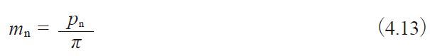
Pitch measured perpendicular to teeth is called normal pitch, pn.
And pn divided by π is then a normal module, mn.
The tooth profile of a helical gear with applied normal module,
mn, and normal pressure angle αn belongs to a normal system.
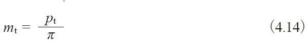
In the axial view, the pitch on the reference is called the transverse pitch, pt . And pt divided by π is the transversemodule, mt.
These transverse module mt and transverse pressure angle αt at are the basic configuration of transverse system helicalgear.
In the normal system, helical gears can be cut by the same gear hob if module mn and pressure angle at are constant, no matter what the value of helix angle β.
It is not that simple in the transverse system. The gear hob design must be altered in accordance with the changing ofhelix angle β, even when the module mt and the pressure angle at are the same.
Obviously, the manufacturing of helical gears is easier with the normal system than with the transverse system in theplane perpendicular to the axis.
When meshing helical gears, they must have the same helix angle but with opposite hands.
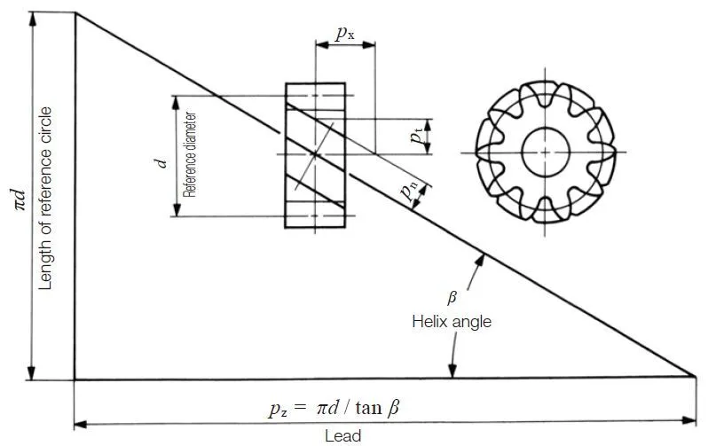
Fig.4.7 Fundamental relationship of a helical gear (Right-hand)
(1) Normal System Helical Gear
In the normal system, the calculation of a profile shifted helical gear, the working pitch diameter dw and transverseworking pressure angle αwt is done per Equations (4.15). That is because meshing of the helical gears in the transverseplane is just like spur gears and the calculation is similar.
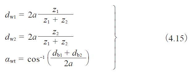
Table 4.9 shows the calculation of profile shifted helical gears in the normal system. If normal profile shift coefficientsxn1, xn2 are zero, they become standard gears.
Table 4.9 The calculations of a profile shifted helical gear in the normal system (1)
| No. | Item | Symbol | Formula | Example | |
| Pinion(1) | Gear(2) | ||||
| 1 | Normal module | mn | Set Value | 3 | |
| 2 | Normal pressure angle | αn | 20 deg | ||
| 3 | Reference cylinder helix angle | β | 30 deg | ||
| 4 | Number of teeth & helical hand | z | 12 (L) | 60 (R) | |
| 5 | Normal coefficient of profile shift | xn | + 0.09809 | 0 | |
| 6 | Transverse pressure angle | αt | 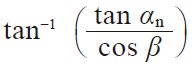 | 22.79588 deg | |
| 7 | Involute function αwt | inv αwt | 0.023405 | ||
| 8 | Transverse working pressure angle | αwt | Find from involute Function Table | 23.1126 deg | |
| 9 | Center distance modification coefficient | y | 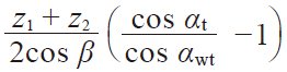 | 0.09744 | |
| 10 | Center distance | a | 125.000 | ||
| 11 | Reference diameter | d | 41.569 | 207.846 | |
| 12 | Base diameter | db | d cos αt | 38.322 | 191.611 |
| 13 | Working pitch diameter | dw |  | 41.667 | 208.333 |
| 14 | Addendum | ha1 ha2 | ( 1 + y – xn2 ) mn ( 1 + y – xn1 ) mn | 3.292 | 2.998 |
| 15 | Tooth depth | h | {2.25 + y – ( Xn1 + Xn2 )}mn | 6.748 | |
| 16 | Tip diameter | da | d + 2ha | 48.153 | 213.842 |
| 17 | Root diameter | df | da – 2h | 34.657 | 200.346 |
If center distance, α, is given, the normal profile shift coefficients xn1 and xn2 can be calculated from Table 4.10.These are the inverse equations from items 5 to 10 of Table 4.9.
Table 4.10 The calculations for a profile shifted helical gear in the normal system (2)
| No. | Item | Symbol | Formula | Example | |
| Pinion (1) | Gear (2) | ||||
| 1 | Center distance | a | Set Value | 125 | |
| 2 | Center distance modification coefficient | y | 0.097447 | ||
| 3 | Transverse working pressure angle | αwt | 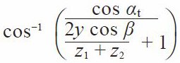 | 23.1126 deg | |
| 4 | Sum of profile shift coefficient | xn1 + xn2 | 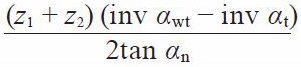 | 0.09809 | |
| 5 | Normal profile shift coefficient | xn | – | 0.09809 | 0 |
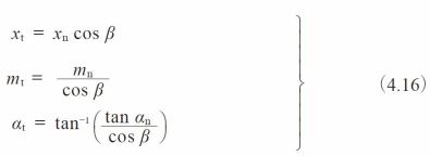
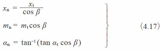
The transformation from a normal system to a transverse system is accomplished by the following equations :
(2) Transverse System Helical Gear
Table 4.11 shows the calculation of profile shifted helical gears in a transverse system. They become standard if xt1=xt2=0.
Table 4.11 The calculations for a profile shifted helical gear in the transverse system (1)
| No. | Item | Symbol | Formula | Example | |
| Pinion(1) | Gear(2) | ||||
| 1 | Transverse module | mt | Set Value | 3 | |
| 2 | Transverse pressure angle | αt | 20 deg | ||
| 3 | Reference cylinder helix angle | β | 30 deg | ||
| 4 | Number of teeth & helical hand | z | 12 (L) | 60 (R) | |
| 5 | Transverse profile shift coefficient | xt | 0.34462 | 0 | |
| 6 | Involute function αwt | inv αwt | 0.0183886 | ||
| 7 | Transverse working pressure angle | αwt | Find from Involute Function Table | 21.3975 deg | |
| 8 | Center distance modification coefficient | y | 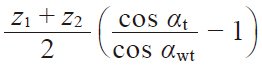 | 0.33333 | |
| 9 | Center distance | a | 109.0000 | ||
| 10 | Reference diameter | d | zmt | 36.000 | 180.000 |
| 11 | Base diameter | db | d cos αt | 33.8289 | 169.1447 |
| 12 | Working pitch diameter | dw | 36.3333 | 181.6667 | |
| 13 | Addendum | ha1 ha2 | ( 1 + y – xt2 ) mt ( 1 + y – xt1 ) mt | 4.000 | 2.966 |
| 14 | Tooth depth | h | {2.25 + y – ( Xt1 + Xt2 )}mt | 6.716 | |
| 15 | Tip diameter | da | d + 2ha | 44.000 | 185.932 |
| 16 | Root diameter | df | da – 2h | 30.568 | 172.500 |
Table 4.12 presents the inverse calculation of item 5 to 9 of Table 4.11.
Table 4.12 The calculations for a profile shifted helical gear in the transverse system (2)
| No. | Item | Symbol | Formula | Example | |
| Pinion (1) | Gear (2) | ||||
| 1 | Center distance | a | Set Value | 109 | |
| 2 | Center distance modification coefficient | y | 0.33333 | ||
| 3 | Transverse working pressure angle | αwt | 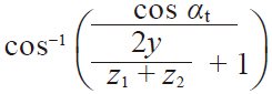 | 21.39752 deg | |
| 4 | Sum of profile shift coefficient | xt1 + xt2 | 0.34462 | ||
| 5 | Transverse profile shift coefficient | xt | – | 0.34462 | 0 |
The transformation from a transverse to a normal system is described by the following equations :
(3) Helical Rack
Viewed in the transverse plane, the meshing of a helical rack and gear is the same as a spur gear and rack. Table 4.13presents the calculation examples for a mated helical rack with normal module and normal pressure angle. Similarily,Table 4.14 presents examples for a helical rack in the transverse system (i.e., perpendicular to gear axis).
Table 4.13 The calculations for a helical rack in the normal system
| No. | Item | Symbol | Formula | Example | |
| Pinion | Rack | ||||
| 1 | Normal module | mn | Set Value | 2.5 | |
| 2 | Normal pressure angle | αn | 20 deg | ||
| 3 | Reference cylinder helix angle | β | 10 deg 57’49” | ||
| 4 | Number of teeth & helical hand | z | 20 (R) | – (L) | |
| 5 | Normal profile shift coefficient | xn | 0 | – | |
| 6 | Pitch line height | H | – | 27.5 | |
| 7 | Transverse pressure angle | αt | 20.34160 deg | ||
| 8 | Mounting distance | a | 52.965 | ||
| 9 | Reference diameter | d | 50.92956 | – | |
| 10 | Base diameter | db | d cos αt | 47.75343 | |
| 11 | Addendum | ha | mn ( 1 + Xn ) | 2.500 | 2.500 |
| 12 | Tooth depth | h | 2.25mn | 5.625 | |
| 13 | Tip diameter | da | d + 2ha | 55.929 | – |
| 14 | Root diameter | df | da – 2h | 44.679 | |
The formulas of a standard helical rack are similar to those of Table 4.14 with only the normal profile shift coefficientxn=0.
To mesh a helical gear to a helical rack, they must have the same helix angle but with opposite hands.
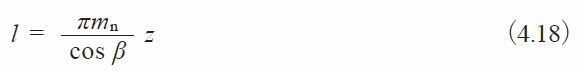
The displacement of the helical rack, l, for one rotation of the mating gear is the product of the transverse pitch andnumber of teeth.
According to the equations of Table 4.13, let transverse pitch pt=8 mm and displacement l=160 mm. The transversepitch and the displacement could be resolved into integers, if the helix angle were chosen properly.
Table 4.14 The calculations for a helical rack in the transverse system
| No. | Item | Symbol | Formula | Example | |
| Pinion | Rack | ||||
| 1 | Transverse module | mt | Set Value | 2.5 | |
| 2 | Transverse pressure angle | αt | 20 deg | ||
| 3 | Reference cylinder helix angle | β | 10 deg 57’49” | ||
| 4 | Number of teeth & helical hand | z | 20 (R) | – (L) | |
| 5 | Transverse profile shift coefficient | xt | 0 | – | |
| 6 | Pitch line height | H | – | 27.5 | |
| 7 | Mounting distance | a | 52.500 | ||
| 8 | Reference diameter | d | zmt | 50.000 | – |
| 9 | Base diameter | db | d cos αt | 46.98463 | |
| 10 | Addendum | ha | mt ( 1 + Xt ) | 2.500 | 2.500 |
| 11 | Tooth depth | h | 2.25mt | 5.625 | |
| 12 | Tip diameter | da | d + 2ha | 55.000 | – |
| 13 | Root diameter | df | da – 2h | 43.750 | |
In the meshing of transverse system helical rack and helical gear, the movement, l, for one turn of the helical gearis the transverse pitch multiplied by the number of teeth.
![]()
4.4 Bevel Gears
Bevel gears, whose pitch surfaces are cones, are used to drive intersecting axes. Bevel gears are classified accordingto their type of the tooth forms into Straight Bevel Gear, Spiral Bevel Gear, Zerol Bevel Gear, Skew Bevel Gear etc.The meshing of bevel gears means the pitch cone of two gears contact and roll with each other. Let z1 and z2 be pinionand gear tooth numbers; shaft angle Σ ; and reference cone angles δ1 and δ2 ; then:
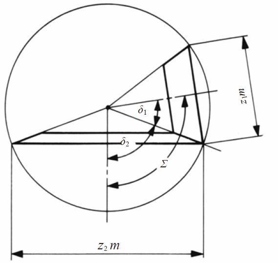
Fig. 4.8 The reference cone angle of bevel gear
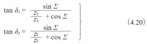
Generally, a shaft angle Σ=90° is most used. Other angles (Figure 4.8) are sometimes used. Then, it is called “bevelgear in nonright angle drive”. The 90° case is called “bevel gear in right angle drive”. When Σ=90°, Equation (4.20)becomes :
Miter gears are bevel gears with Σ=90° and z1=z2. Their transmission ratio z2 / z1=1.
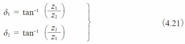
Figure 4.9 depicts the meshing of bevel gears. The meshing must be considered in pairs. It is because the reference coneangles δ1 and δ2 are restricted by the gear ratio z2 / z1. In the facial view, which is normal to the contact line ofpitch cones, the meshing of bevel gears appears to be similar to the meshing of spur gears.
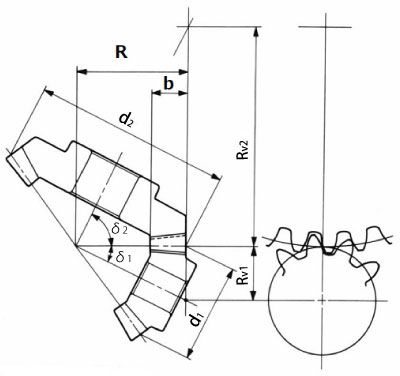
Fig. 4.9 The meshing of bevel gears
(1) Gleason Straight Bevel Gears
A straight bevel gear is a simple form of bevel gear having straight teeth which, if extended inward, would come togetherat the intersection of the shaft axes. Straight bevel gears can be grouped into the Gleason type and the standard type.
In this section, we discuss the Gleason straight bevel gear. The Gleason Company defines the tooth profile as: toothdepth h=2.188m; tip and root clearance c=0.188m; and working depth hw=2.000m.
The characteristics are :
** Design specified profile shifted gears
In the Gleason system, the pinion is positive shifted and the gear is negative shifted. The reason is to distributethe proper strength between the two gears. Miter gears, thus, do not need any shift.
** The tip and root clearance is designed to be parallel
The face cone of the blank is turned parallel to the root cone of the mate in order to eliminate possible fillet interferenceat the small end of the teeth.
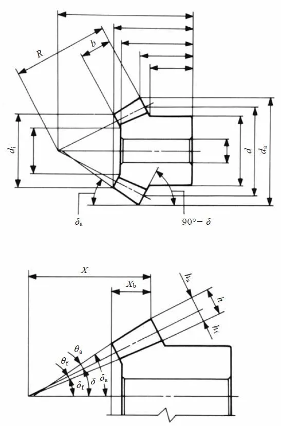
Fig. 4.10 Dimensions and angles of bevel gears
Table 4.15 shows the minimum number of the teeth to prevent undercut in the Gleason system at the shaft angle Σ=90.°
Table 4.15 The minimum numbers of teeth to prevent undercut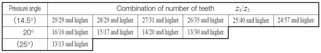
Table 4.16 presents equations for designing straight bevel gears in the Gleason system. The meanings of the dimensionsand angles are shown in Figure 4.10 above. All the equations in Table 4.16 can also be applied to bevel gears with anyshaft angle.
The straight bevel gear with crowning in the Gleason system is called a Coniflex gear. It is manufactured by a specialGleason “Coniflex” machine. It can successfully eliminate poor tooth contact due to improper mounting and assembly.
Tale 4.16 The calculations of straight bevel gears of the Gleason system
| No. | Item | Symbol | Formula | Example | |
| Pinion(1) | Gear(2) | ||||
| 1 | Shaft angle | Σ | Set Value | 90 deg | |
| 2 | Module | m | 3 | ||
| 3 | Reference pressure angle | α | 20 deg | ||
| 4 | Number of teeth | z | 20 | 40 | |
| 5 | Reference diameter | d | zm | 60 | 120 |
| 6 | Reference cone angle | δ1 δ2 | 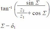 | 26.56505 deg | 63.43495 deg |
| 7 | Cone distance | R | 67.08204 | ||
| 8 | Facewidth | b | It should not exceed R / 3 | 22 | |
| 9 | Addendum | ha1 ha2 | 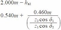 | 4.035 | 1.965 |
| 10 | Dedendum | hf | 2.188m – ha | 2.529 | 4.599 |
| 11 | Dedendum angle | θf | tan^-1(hf / R ) | 2.15903 deg | 3.92194 deg |
| 12 | Addendum angle | θa1 θa2 | θf2 θf1 | 3.92194 deg | 2.15903 deg |
| 13 | Tip angle | δa | σ + θa | 30.48699 deg | 65.59398 deg |
| 14 | Root angle | δf | σ – θf | 24.40602 deg | 59.51301 deg |
| 15 | Tip diameter | da | d + 2ha cos σ | 67.2180 | 121.7575 |
| 16 | Pitch apex to crown | X | R cos σ – ha sin σ | 58.1955 | 28.2425 |
| 17 | Axial facewidth | Xb | 19.0029 | 9.0969 | |
| 18 | Inner tip diameter | di | 44.8425 | 81.6609 | |
The first characteristic of a Gleason Straight Bevel Gear that it is a profile shifted tooth. From Figure 4.11, we cansee the tooth profile of Gleason Straight Bevel Gear and the same of Standard Straight Bevel Gear.
Fig. 4.11 The tooth profile of straight bevel gears
(2) Standard Straight Bevel Gears
A bevel gear with no profile shifted tooth is a standard straight bevel gear. The are also referred to as Klingelnbergbevel gears. The applicable equations are in Table 4.17.
Table 4.17 The calculations for a standard straight bevel gears
| No. | Item | Symbol | Formula | Example | |
| Pinion(1) | Gear(2) | ||||
| 1 | Shaft angle | Σ | Set Value | 90 deg | |
| 2 | Module | m | 3 | ||
| 3 | Reference pressure angle | α | 20 deg | ||
| 4 | Number of teeth | z | 20 | 40 | |
| 5 | Reference diameter | d | zm | 60 | 120 |
| 6 | Reference cone angle | δ1 δ2 | | 26.56505 deg | 63.43495 deg |
| 7 | Cone distance | R | 67.08204 | ||
| 8 | Facewidth | b | It should not exceed R / 3 | 22 | |
| 9 | Addendum | ha1 ha2 | | 4.035 | 1.965 |
| 10 | Dedendum | hf | 2.188m – ha | 2.529 | 4.599 |
| 11 | Dedendum angle | θf | tan^-1(hf / R ) | 2.15903 deg | 3.92194 deg |
| 12 | Addendum angle | θa1 θa2 | θf2 θf1 | 3.92194 deg | 2.15903 deg |
| 13 | Tip angle | δa | σ + θa | 30.48699 deg | 65.59398 deg |
| 14 | Root angle | δf | σ – θf | 24.40602 deg | 59.51301 deg |
| 15 | Tip diameter | da | d + 2ha cos σ | 67.2180 | 121.7575 |
| 16 | Pitch apex to crown | X | R cos σ – ha sin σ | 58.1955 | 28.2425 |
| 17 | Axial facewidth | Xb | 19.0029 | 9.0969 | |
| 18 | Inner tip diameter | di | 44.8425 | 81.6609 | |
These equations can also be applied to bevel gear sets with other than 90° shaft angles.
(3) Gleason Spiral Bevel Gears
A spiral bevel gear is one with a spiral tooth flank as in Figure 4.12. The spiral is generally consistent with thecurve of a cutter with the diameter dc. The spiral angle β is the angle between a generatrix element of the pitch coneand the tooth flank. The spiral angle just at the tooth flank center is called the mean spiral angle βm. In practice,the term spiral angle refers to the mean spiral angle.
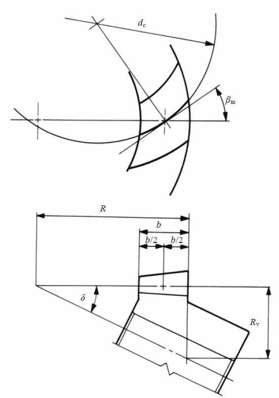
Fig.4.12 Spiral Bevel Gear (Left-hand)
All equations in Table 4.20 are specific to the manufacturing method of Spread Blade or of Single Side from Gleason.If a gear is not cut per the Gleason system, the equations will be different from these.
The tooth profile of a Gleason spiral bevel gear shown here has the tooth depth h=1.888m; tip and root clearance c=0.188m; and working depth hw=1.700m. These Gleason spiral bevel gears belong to a stub gear system. This is applicableto gears with modules m > 2.1.
Table 4.18 shows the minimum number of teeth to avoid undercut in the Gleason system with shaft angle Σ=90° and pressureangle αn=20°.
Table 4.18 The minimum numbers of teeth to prevent undercut β=35°
If the number of teeth is less than 12, Table 4.19 is used to determine the gear sizes.
Table 4.19 Dimentions for pinions with number of teeth less than 12
| Number of teeth in pinion z1 | 6 | 7 | 8 | 9 | 10 | 11 | |
| Number of teeth in gear z2 | 34 and higher | 33 and higher | 32 and higher | 31 and higher | 30 and higher | 29 and higher | |
| Working depth hw | 1.500 | 1.560 | 1.610 | 1.650 | 1.680 | 1.695 | |
| Tooth depth h | 1.666 | 1.733 | 1.788 | 1.832 | 1.865 | 1.882 | |
| Gear addendum ha2 | 0.215 | 0.270 | 0.325 | 0.380 | 0.435 | 0.490 | |
| Pinion addendum ha1 | 1.285 | 1.290 | 1.285 | 1.270 | 1.245 | 1.205 | |
| Tooth thickness of gear s2 | 30 | 0.911 | 0.957 | 0.975 | 0.997 | 1.023 | 1.053 |
| 40 | 0.803 | 0.818 | 0.837 | 0.860 | 0.888 | 0.948 | |
| 50 | - | 0.757 | 0.777 | 0.828 | 0.884 | 0.946 | |
| 60 | - | - | 0.777 | 0.828 | 0.883 | 0.945 | |
| Normal pressure angle αn | 20° | ||||||
| Spiral angle β | 35° - 40° | ||||||
| Shaft angle ∑ | 90° | ||||||
Table 4.20 shows the calculations for spiral bevel gears in the Gleason system
Table 4.20 The calculations for spiral bevel gears in the Gleason system
| No. | Item | Symbol | Formula | Example | |
| Pinion (1) | Gesr (2) | ||||
| 1 | Shaft angle | ∑ | Set Value | 90 deg | |
| 2 | Module | m | 3 | ||
| 3 | Normal pressure angle | αn | 20 deg | ||
| 4 | Mean spiral angle | βm | 35 deg | ||
| 5 | Number of teeth and spiral hand | z | 20 (L) | 40 (R) | |
| 6 | Transverse pressure angle | αt | 23.95680 | ||
| 7 | Reference diameter | d | zm | 60 | 120 |
| 8 | Reference cone angle | σ1 σ2 | 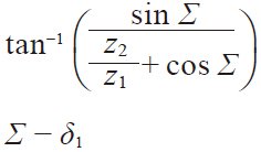 | 26.56505 deg | 63.43495 deg |
| 9 | Cone distance | R | 67.08204 | ||
| 10 | Facewidth | b | It should be less than 0.3R or 10m | 20 | |
| 11 | Addendum | ha1 ha2 | 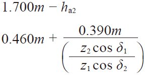 | 3.4275 | 1.6725 |
| 12 | Dedendum | hf | 1.888m – ha | 2.2365 | 3.9915 |
| 13 | Dedendum angle | θf | tan^-1( hf / R ) | 1.90952 deg | 3.40519 deg |
| 14 | Addendum angle | θa1 θa2 | θf2 θf1 | 29.97024 deg | 1.90952 deg |
| 15 | Tip angle | σa | σ + θa | 29.97024 deg | 65.34447 deg |
| 16 | Root angle | σf | σ – θf | 24.65553 deg | 60.02976 deg |
| 17 | Tip diameter | da | d + 2ha cos σ | 66.1313 | 121.4959 |
| 18 | Pitch apex to crown | X | R cos σ – ha sin σ | 58.4672 | 28.5041 |
| 19 | Axial facewidth | Xb | 17.3565 | 8.3479 | |
| 20 | Inner tip diameter | di | 46.1140 | 85.1224 | |
All equations in Table 4.20 are also applicable to Gleason bevel gears with any shaft angle. A spiral bevel gear setrequires matching of hands; left-hand and right-hand as a pair.
(4) Gleason Zerol Bevel Gears
When the spiral angle bm=0, the bevel gear is called a Zerol bevel gear. The calculation equations of Table 4.16for Gleason straight bevel gears are applicable. They also should take care again of the rule of hands; left and rightof a pair must be matched. Figure 4.13 is a left-hand Zerol bevel gear.
Fig. 4.13 Left-hand zerol bevel gear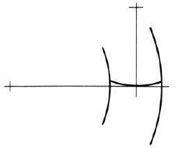
4.5 Screw Gears
Screw gearing includes various types of gears used to drive nonparallel and nonintersecting shafts where the teeth ofone or both members of the pair are of screw form. Figure 4.14 shows the meshing of screw gears. Two screw gears canonly mesh together under the conditions that normal modules (mn1) and (mn2) and normal pressure angles (αn1, αn2) arethe same.
Fig.4.14 Screw gears of nonparallel and nonintersecting axes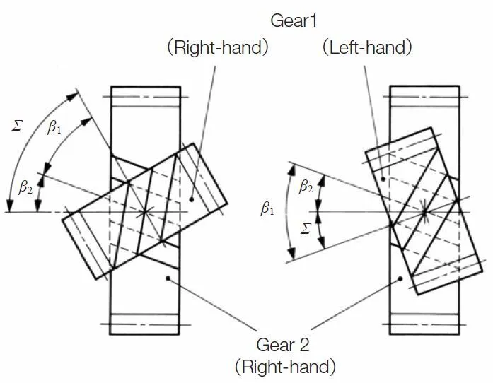
Let a pair of screw gears have the shaft angle Σ and helix angles β1 and β2 :
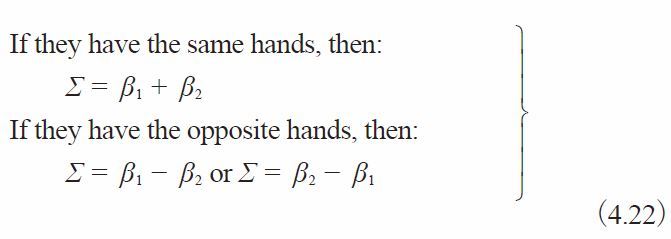
If the screw gears were profile shifted, the meshing would become a little more complex. Let βw1, βw2 represent the working pitch cylinder ;
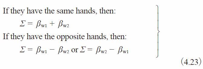
Table 4.21 presents equations for a profile shifted screw gear pair. When the normal profile shift coefficients xn1=xn2=0, the equations and calculations are the same as for standard gears.
Table 4.21 The equations for a screw gear pair on nonparallel and Nonintersecting axes in the normal system
| No. | Item | Symbol | Formula | Example | |
| Pinion (1) | Gear (2) | ||||
| 1 | Normal module | mn | Set Value | 3 | |
| 2 | Normal pressure angle | αn | 20 deg | ||
| 3 | Reference cylinder helix angle | β | 20 deg | 30 deg | |
| 4 | Number of teeth & helical hand | z | 15 (R) | 24 (R) | |
| 5 | Normal profile shift coefficient | xn | 0.4 | 0.2 | |
| 6 | Number of teeth of an Equivalent spur gear | zv | 18.0773 | 36.9504 | |
| 7 | Transverse pressure angle | αt | 21.1728 deg | 22.7959 deg | |
| 8 | Involute function αwn | inv αwn | 0.0228415 | ||
| 9 | Normal working pressure angle | αwn | Find from involute function table | 22.9338 deg | |
| 10 | Transverse working pressure angle | αwn | 24.2404 deg | 26.0386 deg | |
| 11 | Center distance modification coefficient | y | 0.55977 | ||
| 12 | Center distance | a | 67.1925 | ||
| 13 | Reference diameter | d | 47.8880 | 83.1384 | |
| 14 | Base diameter | db | d cos αt | 44.6553 | 76.6445 |
| 15 | Working pitch diameter | dw1 dw2 | 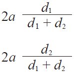 | 49.1155 | 85.2695 |
| 16 | Working helix angle | βw | 20.4706 deg | 30.6319 deg | |
| 17 | Shaft angle | ∑ | βw1 + βw2 or βw1 – βw2 | 51.1025 deg | |
| 18 | Addendum | ha1 ha2 | ( 1 + y – xn2 ) mn ( 1 + y – xn1 ) mn | 4.0793 | 3.4793 |
| 19 | Tooth depth | h | {2.25 + y – ( xn1 + xn2 )}mn | 6.6293 | |
| 20 | Tip diameter | da | d + 2ha | 56.0466 | 90.0970 |
| 21 | Root diameter | df | da – 2h | 42.7880 | 76.8384 |
Standard screw gears have relations as follows:
dw1=d1
dw2=d2
βw1=β1
βw2=β2
(4.24)
Appendix – What is screw gear ?
This article is reproduced with the permission.
Masao Kubota,Haguruma Nyumon, Tokyo : Ohmsha, Ltd., 1963.
The screw gear (or crossed helical gear) in pic 5.1 is a type of gear whose two axes are neither parallel nor crossed(skew gears), and whose pitch surface consists of two cylindrical surfaces circumscribing at one point on the shortestdistance between the two axes. The screw gear is a point contact gear which consists of obliquely meshed helical gearswhose sum or difference of torsion angle of tooth traces is equal to the included angle of the two axes.
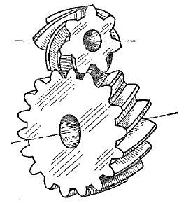
Pic 5.1 Screw gear
Background of screw gear
In Pic 5.2, the point P at one point on the shortest distance between two axes is called pitch point, where two cylinders with radius R1 or R2 whose axes I and II constitute the center distance A and included angle circumscribe at the point P.
Assuming that the two cylinders are reference curved surfaces for making gear teeth, and the gears mesh at the pitchpoint P and its neighborhood. In order that both tooth flanks make contact at the point P to transmit motion, theyneed to share the normal line, and the velocity component of the both gears in the direction of normal line of thetooth flanks need to be equal. Therefore, at the point P, the direction of the tooth traces should be same, and thevelocity component of the both gears at right angle to the tooth traces should be equal. More specifically, as in Pic5.2, the direction of the vertical line from the point P toward the directions of the vectors of gear speed V1 and V2 at the point P equals to the velocity component of both gears (Vn), and the right angle (TT) to this direction at the point P becomes the tooth trace’s direction at the pointP. The velocity components of V1 and V2 are not equal in the direction TT. That is to say, there is a slide in the direction of the tooth trace.
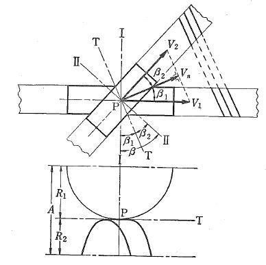
Pic 5.2 Screw gear’s background
Assuming that there is a helical rack, which has the tooth trace in the direction TT and its tangential plane of both pitch cylinders at the point P is the pitch plane. When it moves with a velocity of Vn, the curve formed on each gear as an envelope surface of the rack tooth flank becomes the tooth flank of bothgears. When the tooth flank of the helical rack is plane, the tooth flank of both gears becomes an involute helicoid.It is an involute screw gear, and its normal section is an involute tooth profile.
The simultaneous contact line of the tooth flank of each gear and rack is the trace of a foot of a perpendicular fromthe arbitrary point on each pitch cylinder’s bus to the rack tooth surface through the pitch point P (it becomes astraight line for involute screw gear). Both traces cross at the foot of a perpendicular from the pitch point P tothe rack tooth profile. (See Pic 5.3 (a) NA and NB) Therefore, both tooth profiles point-contact at that point.
The trace of the contact point is generally the curve through the pitch point P. As for the involute screw gear, thetrace of the contact point becomes a straight line W which passes through the pitch point P, because the plane of therack tooth profile moves parallel. The line is called action line (see Pic 5.3), the crossing line of tangential planes of base cylinders of gears, and it is alsothe fixed line contacts with both base cylinders. Same as normal gears, the angular velocity ratio is equal to thereciprocal ratio of the number of teeth, and the normal plane module should be equal for both gears.
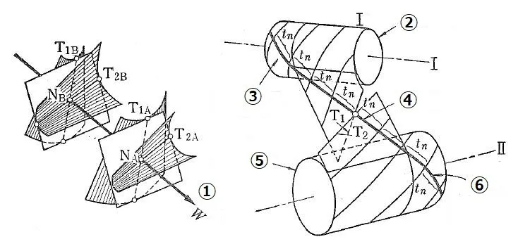
Pic 5.3 Mesh of involute screw gear
Left Picture – Contact of screw gear’s flank
(1) Action line
Right Picture – Relation of base cylinders, action line, tangential plane, tooth trace of screw gear
(2) Base cylinder of gear I
(3) Screw line orthogonal to tooth trace
(4) Action line
(5) Base cylinder of gear II
(6) Screw line orthogonal to tooth trace
Suppose that the helical angle of the tooth trace is β1 and β2, the normal plane module of helical rack is mn, and the number of teeth of each gear is z1 and z2, the radius of pitch cylinders R1 and R2 are :
R1=z1mn / 2cosβ1, R2=z2mn / 2cosβ2
Then, R1 + R2=A, β1 + β2=β
Therefore, 2A / mn=z1 / cosβ1 + z2 / cos(β – β1)
For example, when A, β, z1, z2 and mn are given, β1 and β2 are defined by the preceding formula. However, β1>0, β2>0 in the preceding picture.β1 and β2could be 0 or negative number. In fact, β=90° in many cases. When β=90°, to minimize center distance, setdA / dβ1=0 and obtain![]()
Application of screw gear
As screw gears are point-contact, the contact stress at the contact point is large and lubricant film is easy to becomethinner and as a result, the gears easily wear out. Therefore, the screw gears are not suitable for transmitting largepower. On the other hand, the gears mesh smoothly and easy to do cut adjustment, so frequently used for transmissionmechanism between skew shafts whose center distance is in the middle. In addition, it is well known that the meshingrelation of cutter and machined gear at gear shaving is similar to screw gears. The meshing relation of hob and gearsto be cut is also similar to screw gears.
When one of screw gears (driven gear) is a rack gear, they can line-contact and transmit heavy load. They may be usedfor the table drive of a planning machine. The rack type shaving cutter can be used, too.
Only the curve which goes on each tooth flank diagonally through the pitch point is useful for meshing of tooth flankof screw gears, and therefore the working face width is limited. However, enlarging the face width a little and enablingthe gears to move toward the axis will avoid excessive local wear, and lengthens the life of the entire gear.
4.6 Cylindrical Worm Gear Pair
Cylindrical worms may be considered cylindrical type gears with screw threads. Generally, the mesh has a 90° shaft angle.The number of threads in the worm is equivalent to the number of teeth in a gear of a screw type gear mesh. Thus, aonethread worm is equivalent to a one-tooth gear; and two-threads equivalent to two-teeth, etc. Referring to Figure4.15, for a reference cylinder lead angle γ, measured on the pitch cylinder, each rotation of the worm makes the threadadvance one lead pz.
There are four worm tooth profiles in JIS B 1723-1977, as defined below.
Type I : The tooth profile is trapezoidal on the axial plane.
Type II : The tooth profile is trapezoid on the plane normal to the space.
Type III : The tooth profile which is obtained by inclining the axis of the milling or grinding, of which cutter shapeis trapezoidal on the cutter axis, by the lead angle to the worm axis.
Type IV : The tooth profile is of involute curve on the plane of rotation.
KHK stock worm gear products are all Type III. Worm profiles (Fig 4.15). The cutting tool used to process worm gearsis called a single-cutter that has a single-edged blade. The cutting of worm gears is done with worm cutting machine.Because the worm mesh couples nonparallel and nonintersecting axes, the axial plane of worm does not correspond withthe axial plane of worm wheel. The axial plane of worm corresponds with the transverse plane of worm wheel. The transverseplane of worm corresponds with the axial plane of worm wheel. The common plane of the worm and worm wheel is the normalplane. Using the normal module, mn, is most popular. Then, an ordinary hob can be used to cut the worm wheel.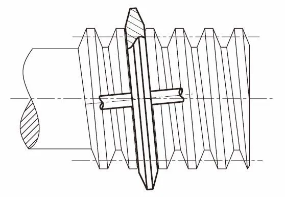
Fig. 4.15 Cutting – Grinding for Type III Worm
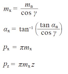
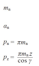
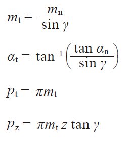
Table 4.22 presents the relationships among worm and worm wheel with regard to axial plane, transverse plane, normalplane, module, pressure angle, pitch and lead.
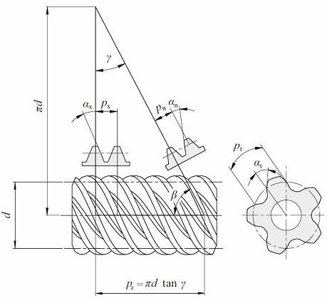
Fig. 4.16 Cylindrical worm (Right-hand)
Table 4.22 The relations of cross sections of worm gear pairs
| Worm | ||
| Axial plane | Normal plane | Transverse plane |
 |  |  |
| Transverse plane | Normal plane | Axial plane |
| Worm wheel | ||
Reference to Figure 4.16 can help the understanding of the relationships in Table 4.22. They are similar to the relationsin Formulas (4.16) and (4.17) in that the helix angle β be substituted by (90 deg – γ). We can consider thata worm with lead angle γ is almost the same as a helical gear with helix angle (90 deg – γ).
(1) Axial Module Worm Gear Pair
Table 4.23 presents the equations, for dimensions shown in Figure 4.16, for worm gears with axial module, mx, andnormal pressure angle αn=20°.
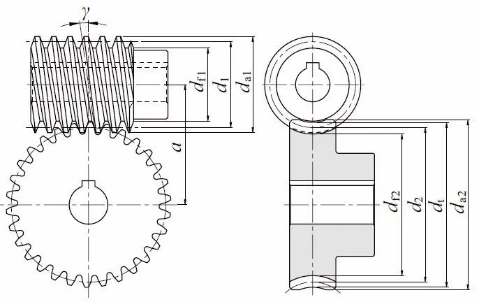
Fig. 4.17 Dimentions of cylindrical worm gear pair
Table 4.23 The calculations for an axial module system worm gear pair
| No. | Item | Symbol | Formula | Example | |
| Worm (1) | Wheel (2) | ||||
| 1 | Axial module | mx | Set Value | 3 | |
| 2 | Normal pressure angle | ( αn ) | ( 20 deg ) | ||
| 3 | No. of threads, no. of teeth | z | Double Thread (R) | 30 (R) | |
| 4 | Coefficient of Profile shift | zt2 | – | 0 | |
| 5 | Reference diameter | d1 d2 | ( Qmx) NOTE1 z2mx | 44.000 | 90.000 |
| 6 | Reference cylinder lead angle | γ | 7.76517 deg | ||
| 7 | Center distance | a | 67.000 | ||
| 8 | Addendum | ha1 ha2 | 1.00 mx ( 1.00 + xt2 ) mx | 3.000 | 3.000 |
| 9 | Tooth depth | h | 2.25 mx | 6.750 | |
| 10 | Tip diameter | da1 da2 | d1 + 2ha1 d2 + 2ha2 + mx NOTE2 | 50.000 | 99.000 |
| 11 | Throat diameter | dt | d2 + 2ha2 | – | 96.000 |
| 12 | Throat surface radius | ri | – | 19.000 | |
| 13 | Root diameter | df1 df2 | da1 – 2h dt – 2h | 36.500 | 82.500 |
NOTE 1.
Diameter factor, Q, means reference diameter of worm, d1, over axial module, mx.
Q=d1 / mx
NOTE 2.
There are several calculation methods of worm wheel tip diameter da2 besides those in Table 4.25.
NOTE 3.
The facewidth of worm, b1, would be sufficient if: b1=πmx (4.5 + 0.02z2)
NOTE 4.
Effective facewidth of worm wheel bw=![]()
So the actual facewidth of b2 ≧ bw + 1.5mx would be enough.
(2) Normal Module System Worm Gear Pair
The equations for normal module system worm gears are based on a normal module, mn, and normal pressure angle, αn=20°. See Table 4.24.
Table 4.24 The calculations for a normal module system worm gear pair
| No. | Item | Symbol | Formula | Example | |
| Worm (1) | Wheel (2) | ||||
| 1 | Normal module | mn | Set Value | 3 | |
| 2 | Normal pressure angle | αn | ( 20 deg ) | ||
| 3 | No. of threads, No. of teeth | z | Double (R) | 30 (R) | |
| 4 | Reference diameter of worm | d1 | 44.000 | – | |
| 5 | Normal profile shift coefficient | xn2 | – | – 0.1414 | |
| 6 | Reference cylinder lead angle | γ | 7.83748 deg | ||
| 7 | Reference diameter of worm wheel | d2 | – | 90.8486 | |
| 8 | Center distance | a | 67.000 | ||
| 9 | Addendum | ha1 ha2 | 1.00 mn ( 1.00 + xn2 ) mn | 3.000 | 2.5758 |
| 10 | Tooth depth | h | 2.25 mn | 6.75 | |
| 11 | Tip diameter | da1 da2 | d1 + 2ha1 dt2 + 2ha1 + mn | 50.000 | 99.000 |
| 12 | Throat diameter | dt | d2 + 2ha2 | – | 96.000 |
| 13 | Throat surface radius | ri | – | 19.000 | |
| 14 | Root diameter | df1 df2 | da1 – 2h dt – 2h | 36.500 | 82.500 |
NOTE : All notes are the same as those of Table 4.23.
(3) Crowning of the Tooth
Crowning is critically important to worm gears. Not only can it eliminate abnormal tooth contact due to incorrectassembly, but it also provides for the forming of an oil film, which enhances the lubrication effect of the mesh. Thiscan favorably impact endurance and transmission efficiency of the worm mesh. There are four methods of crowning wormgear pair :
(a) Cut Worm Wheel with a Hob Cutter of Greater Reference Diameter than the Worm.
A crownless worm wheel results when it is made by using a hob that has an identical pitch diameter as that of theworm. This crownless worm wheel is very difficult to assemble correctly. Proper tooth contact and a complete oil filmare usually not possible.
However, it is relatively easy to obtain a crowned worm wheel by cutting it with a hob whose reference diameter isslightly larger than that of the worm.
This is shown in Figure 4.18. This creates teeth contact in the center region with space for oil film formation.
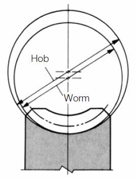
Fig.4.18 The method of using a greater diameter hob
(b) Recut With Hob Center Position Adjustment.
The first step is to cut the worm wheel at standard center distance. This results in no crowning. Then the worm wheelis finished with the same hob by recutting with the hob axis shifted parallel to the worm wheel axis by ±Δh. This resultsin a crowning effect, shown in Figure 4.19.
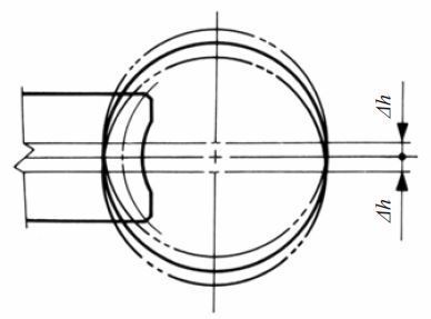
Fig.4.19 Offsetting up or down
(c) Hob Axis Inclining Δθ From Standard Position.
In standard cutting, the hob axis is oriented at the proper angle to the worm wheel axis. After that, the hob axisis shifted slightly left and then right, Δθ, in a plane parallel to the worm wheel axis, to cut a crown effect on theworm wheel tooth.
This is shown in Figure 4.20. Only method (a) is popular. Methods (b) and (c) are seldom used.
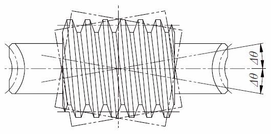
Fig. 4.20 Inclining right or left
(d) Use a Worm with a Larger Pressure Angle than the Worm Wheel.
This is a very complex method, both theoretically and practically. Usually, the crowning is done to the worm wheel,but in this method the modification is on the worm. That is, to change the pressure angle and pitch of the worm withoutchanging base pitch, in accordance with the relationships shown in Equations 4.25 :![]()
In order to raise the pressure angle from before change, αwx, to after change, αx , it is necessary to increase theaxial pitch, pwx, to a new value, px, per Equation (4.25). The amount of crowning is represented as the space betweenthe worm and worm wheel at the meshing point A in Figure 4.22. This amount may be approximated by the following equation:
![]()
Where
d1 : Reference diameter of worm
k : Factor from Table 4.25 and Figure 4.21
Table 4.25 The value of factor k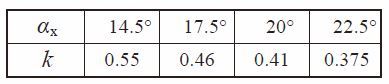
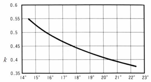
Axial pressure angle αx
Fig. 4.21 The value of factor (k)
Table 4.26 shows an example of calculating worm crowning.
Table 4.26 The calculations for worm crowning
| No. | Item | Symbol | Formula | Example | |
| 1 | Axial module | mwx | NOTE: | 3 | |
| 2 | Normal pressure angle | αwn | 20 deg | ||
| 3 | Number of threads of worm | z1 | 2 | ||
| 4 | Reference diameter of worm | d1 | 44.000 | ||
| 5 | Reference cylinder lead angle | γw | 7.765166 deg | ||
| 6 | Axial pressure angle | αwx | 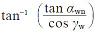 | 20.170236 deg | |
| 7 | Axial pitch | Pwx | πmwx | 9.424778 | |
| 8 | Lead | PwZ | πmwx z1 | 18.849556 | |
| 9 | Amount of crowning | CR | It should be determined by considering the size of tooth contact. | 0.04 | |
| 10 | Factor | k | From Table 4.26 | 0.41 | |
| * After crowning | |||||
| 11 | Axial pitch | Px | 9.466573 | ||
| 12 | Axial pressure angle | αx | 20.847973 deg | ||
| 13 | Axial module | mx | 3.013304 | ||
| 14 | Reference cylinder lead angle | γ | 7.799179 deg | ||
| 15 | Normal pressure angle | αn | tan^-1(tanαx cos γ) | 20.671494 deg | |
| 16 | Lead | Pz | πmx z1 | 18.933146 deg | |
(4) Self-Locking Of Worm Gear Pairs
Self-locking is a unique characteristic of worm meshes that can be put to advantage. It is the feature that a wormcannot be driven by the worm wheel. It is very useful in the design of some equipment, such as lifting, in that thedrive can stop at any position without concern that it can slip in reverse. However, in some situations it can be detrimentalif the system requires reverse sensitivity, such as a servomechanism.
Self-locking does not occur in all worm meshes, since it requires special conditions as outlined here. In this analysis,only the driving force acting upon the tooth surfaces is considered without any regard to losses due to bearing friction,lubricant agitation, etc. The governing conditions are as follows :
Let Ft1=tangential driving force of worm
Then,
Ft1=Fn (cos αn sin γ – μ cos γ) (4.27)
If Ft1 > 0 then there is no self-locking effect at all. Therefore,
Ft1 ≤ 0 is the critical limit of self-locking.
Let αn in Equation (4.27) be 20°, then the condition:
Ft1 ≤ 0 will become :
(cos 20° sing – mcosg) ≤ 0
Figure 4.22 shows the critical limit of self-locking for lead angle g and coefficient of friction m. Practically, itis very hard to assess the exact value of coefficient of friction μ. Further, the bearing loss, lubricant agitationloss, etc. can add many side effects. Therefore, it is not easy to establish precise self-locking conditions.
However, it is true that the smaller the lead angle γ, the more likely the self-locking condition will occur.
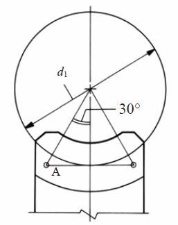
Fig.4.22 Position A is the point of determining crowning amount
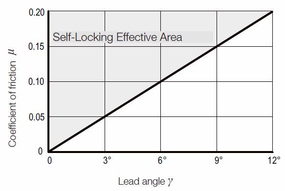
Fig. 4.23 The critical limit of self-locking of lead angle g and coefficient of friction m
Related links :
齿轮模数
齿轮尺寸计算
Free Gear Calculator
Basic Gear Terminology and Calculation