


Generally, bending strength and durability specifications are applied to spur gears and helical gears (including double helical and internal gears) to beused in industrial machines in the following range:
Module m 1.5-25mm
Pitch diameter d0 25-3200mm
Tangential speed v 25m/s or slower
Rotational speed n 3600 rpm or slower
(1) Conversion Formulas
The equations that relate transmitted tangential force at the pitch circle , Ft(kgf), power P(kW), and torque, T(kgf・m) are basic to the calculations. The relations are as follows:
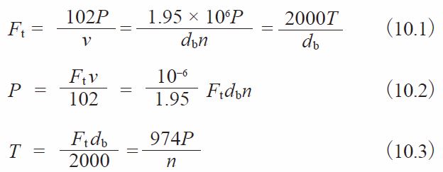
Where v :Tangential speed of working pitch circle (m/s)
v = dbn / 19100
db :Working pitch diameter (mm)
n :Rotational speed (rpm)
(2) Bending Strength Equations
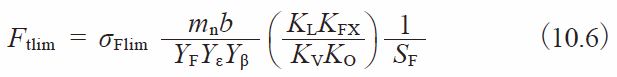
In order to satisfy the bending strength, the transmitted tangential force at the working pitch circle, Ft , is not to exceed the allowable tangential force at the working pitch circle, Ftlim, that is calculated taking into account the allowable bending stress at the root.
![]()
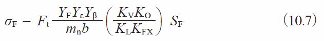
At the same time, the actual bending stress at the root, σF, that is calculated on the basis of the transmitted tangential force at the working pitch circle, Ft, must be less than the allowable bending stress at the root, σFlim.
![]()
Equation (10.6) presents the calculation of Ftlim (kgf).
Equation (10.6) can be converted into stress by Equation (10.7) (kgf/mm2).
(3) Determination of Factors
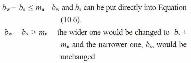
(3)-1 Facewidth b(mm)
If the gears in a pair have different facewidth, let the wider one be bw and the narrower one be bs.
And if:
NOTE: Regarding the facewidth of round gear racks , see 10.2 (3) – 1.
(3)-2 Tooth Profile Factor YF
The tooth profile factor YF is obtainable from Figure 10.1 based on the equivalent number of teeth, zV, and profile shift coefficient, x, if the gear has a standard tooth profile with pressure angle αn = 20°, per JIS B 1701. Figure 10.1 also indicates (a) theoretical undercut limit, and (b) narrow tooth top limit. These will be helpful in determining gear specifications. For internal gears, obtain the factor by considering the equivalent racks.
(3)-3 Load Sharing Factor, Yε
Load sharing factor, Yε, is the reciprocal of transverse contact ratio, εa.
![]()
Fig.10.1 Chart showing tooth profile factor
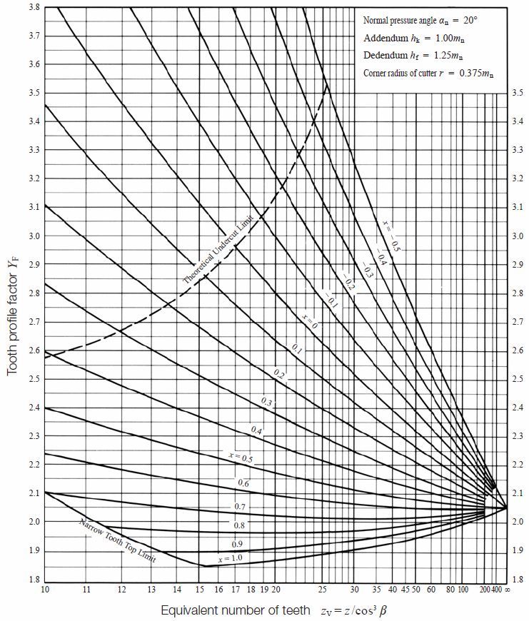
Table 10.1 Transverse contact ratio of standard spur gears, εα
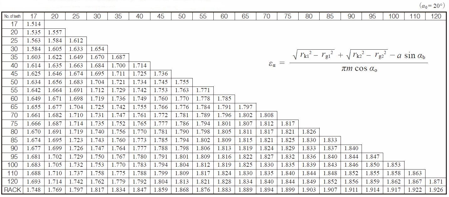
Transverse Contact Ratio is calculated as follows.
For Spur Gears :
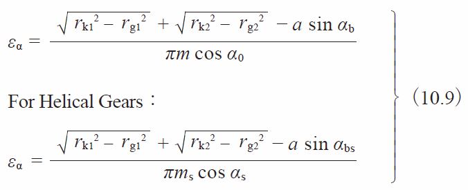
Where:
rk : Tip diameter (mm)
αb : Working pressure angle (degree)
rg : Reference radius (mm)
αbs : Transverse working pressure angle (degree)
a : Center distance (mm)
α0 : Reference pressure angle (degree)
αs : Reference transverse pressure angle (degree)
Table 10.1 shows the transverse contact ratio εa of a standard spur gear (α0 = 20°)
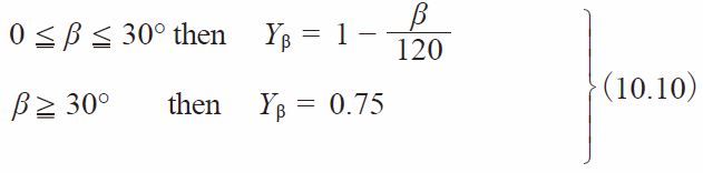
(3)-4 Helix Angle Factor, Y
β
Helix angle factor, Y
β, can be obtained from Equation
(3)-5 Life Factor, KL
We can choose the proper life factor, KL, from Table 10.2. The number of cyclic repetitions means the total loaded meshing during its lifetime.
Table 10.2 Life factor
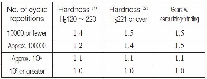
NOTES
(1) Cast steel gears apply to this column.
(2) For induction hardened gears, use the core hardness.
(3)-6 Size Factor of Root Stress, KFX
Generally, this factor, KFX, is unity.
![]()
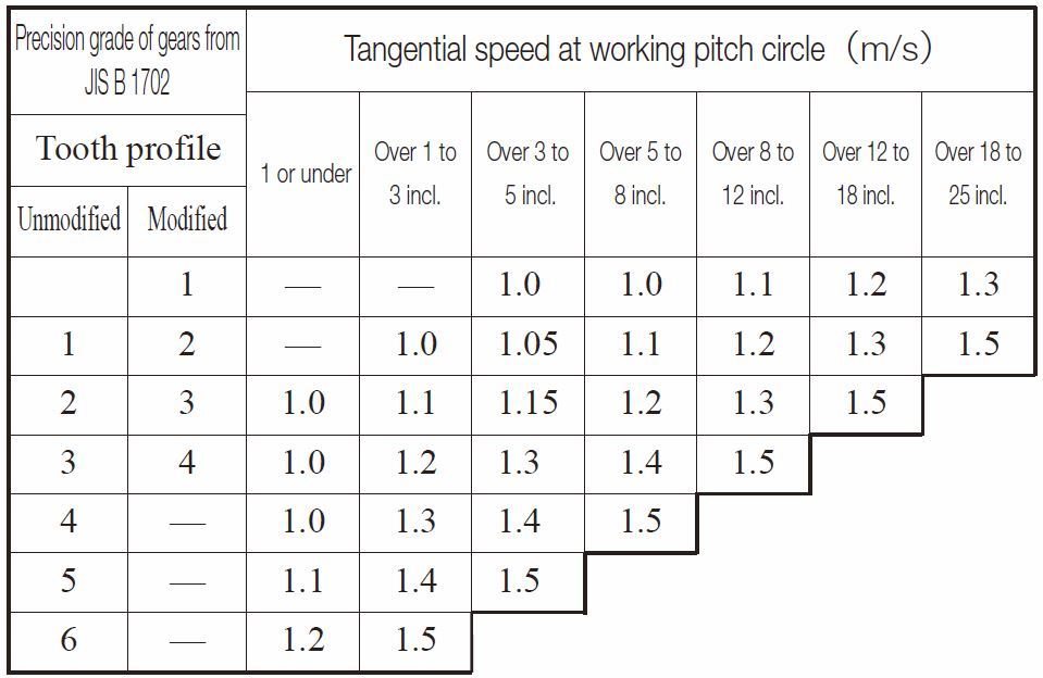
(3)-7 Dynamic Load Factor, KV
Dynamic load factor, KV, can be obtained from Table 10.3 based on the precision of the gear and the tangential speed at working pitch circle.
Table 10.3 Dynamic load factor, KV
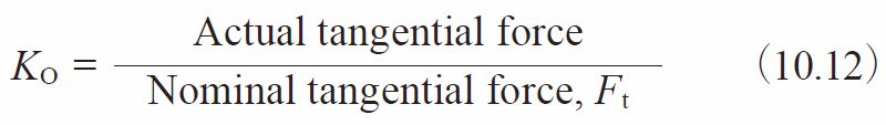
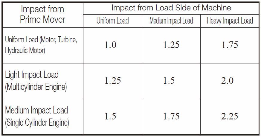
(3)-8 Overload Factor KO
Overload factor, KO, can be obtained from Equation
If tangential force is unknown, Table 10.4 provides guiding values. Load grades on affected machinery are introduced on page 572, as reference.
Table 10.4 Overload Factor, KO
(3)-9 Safety Factor for Bending Failure, SF
Safety factor, SF, is too complicated to be determined precisely. Usually, it is set to at least 1.2.
(3)-10 Allowable Bending Stress at Root, σFlim
For a unidirectionally loaded gear, the allowable bending stresses at the root, σFlim, are shown in Tables 10.5 to 10.9. In these tables, the value of σFlim is the quotient of the fatigue limit under pulsating tension divided by the stress concentration factor 1.4. If the load is bidirectional, and both sides of the tooth are equally loaded, the value of allowable bending stress, σFlim, should be taken as 2/3 of the given value in the table. The core hardness means the hardness at the center region of the root.
Table 10.5 Gears without surface hardening
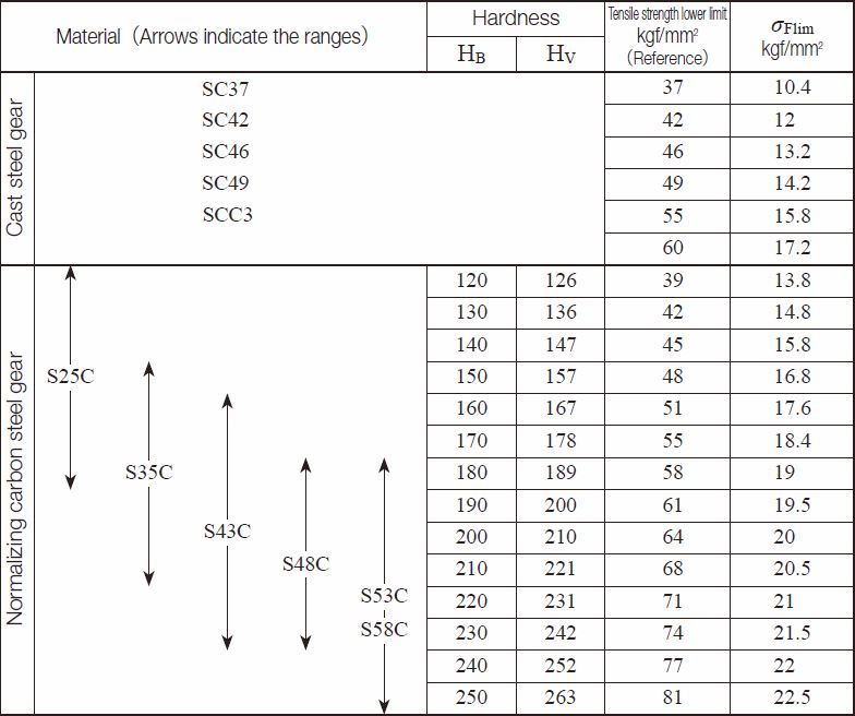
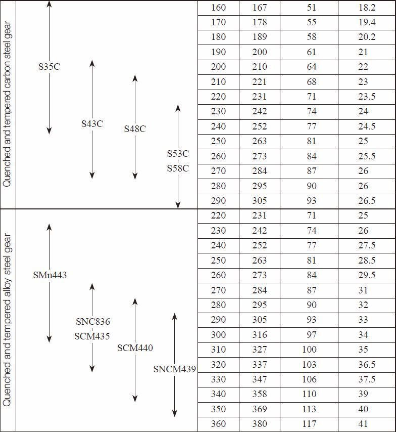
Table 10.6 Induction hardened gears
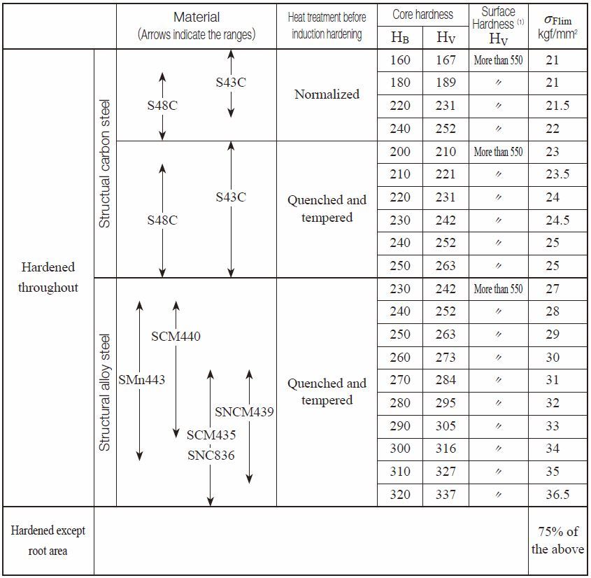
Remarks:If a gear is not quenched completely, or not evenly, or has quenching cracks, the σFlim will drop dramatically.
NOTE (1) : If the hardness after quenching is relatively low, the value of σFlim should be that given in Table 10.5.
Table 10.7 Carburized and quenched gears
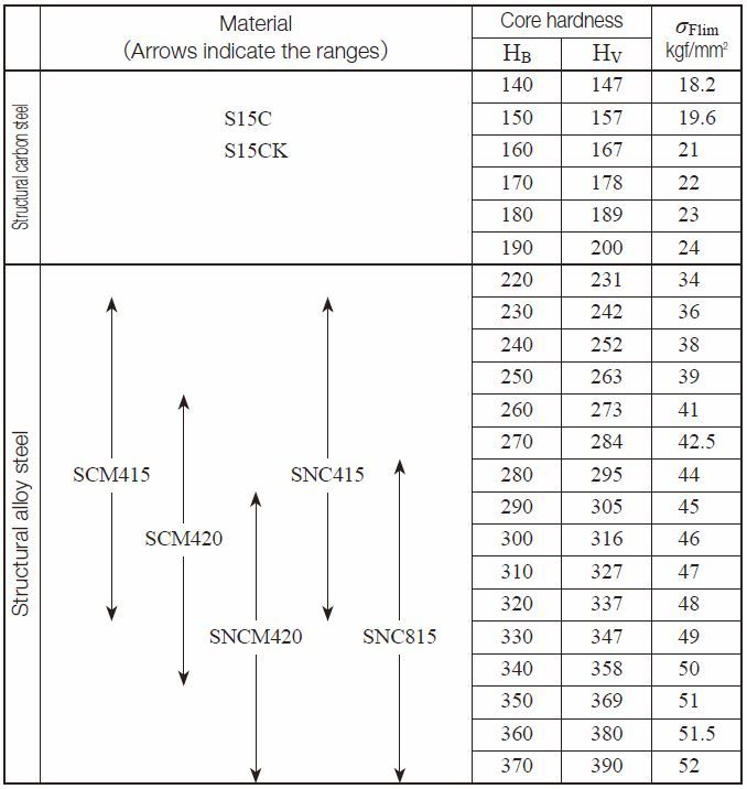
NOTE (2)
The table on the left only applies to those gears which have adequate carburized depth and surface hardness.
If the carburized depth is relatively thin, the value of σFlim should be stated for quenched/tempered gears,
having no surface hardened.
Table 10.8 Nitrided Gears Excerpted from JGMA403-01(1976)
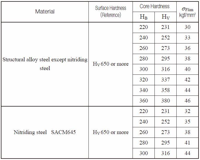
NOTE (1)
The table on the left only applies to those gears which have adequate nitrided depth.
If the nitrided depth is relatively thin, the value of σFlim should be stated for gears which have no surface hardened.
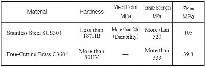
Table 10.9 Stainless Steel and Free-Cutting Brass Gears Excerpted from JGMA6101-02 (2007)
(Reference) Load Grades on Affected Machinery Quoted from JGMA402-01 (1975)
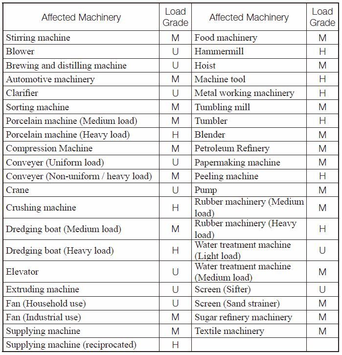
NOTE
1.
This sheet was created in reference to AGMA 151.02
2.
In this sheet, symbols are used to classify what load grades are:
U: Uniform load, M: Medium load and
H: Heavy load
3.
This sheet indicates general tendency of load grades.
For use in heavy load, one-higher-grade should be adopted.
For details, please refer to the AGMA standard mentioned in NOTE 1.
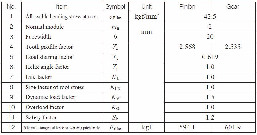
(4) Example of Calculation
Spur gear design details
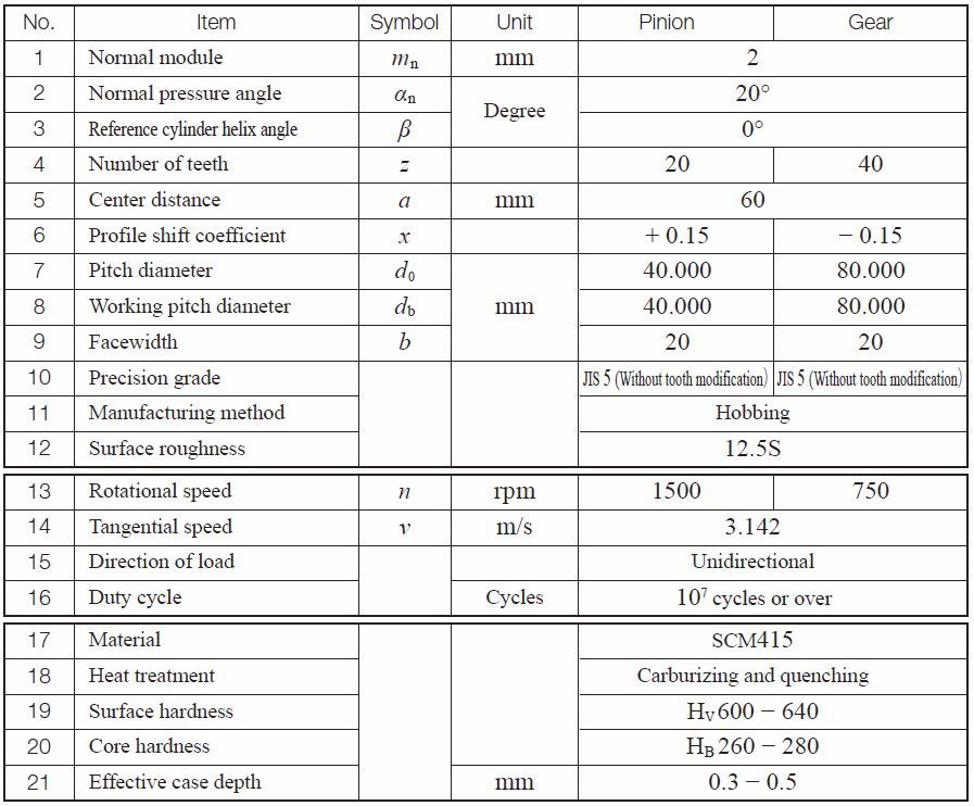
Bending Strength Factors of Spur Gear
Related links / 相关链接 :
齿轮的强度
Strength and Durability of Gears – A page of The ABC’s of Gears / Basic Guide – B