


- TOP >
- Gear Knowledge >
- Gear design procedure in practical design >
- Executing the drawings of the parts related to the gears
Example of executing a drawing of a gear
This time we execute the drawings of the previously designed gear box assembly’s main parts.
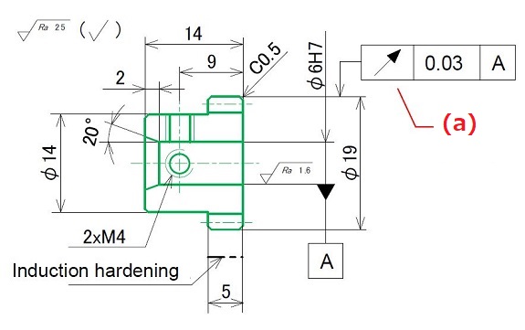
1. Execute the drawing of the small gear "1"
For the drawing of a gear, write the dimensions of the shape before the gear is machined (so-called the blank) on the projection drawing, and write the basic elements of tooth in the list shown in the same drawing. (Figure 5-1)
| Spur gear | ||||
| Gear profile | Standard | Finishing method | Hobbing | |
| Tool | Profile | Standard full depth | Accuracy | JIS B 1702 Grade 4 |
| Module | 1.0 | Remark Number of teeth of mating gear: 34 Shift of mating gear: 0 Center distance: 25.5 Material / S45C Heat treatment / Induction hardening Hardness / (d) HRC45-55 Surface treatment / Black oxide except tooth face |
||
| Pressure angle | 20° | |||
| Number of teeth | 17 | |||
| Pitch diameter | 17 | |||
| Profile shift coefficient | 0 | |||
| Total depth | 2.25 | |||
| Thickness | Base tangent length | (b) 4.67 (c)(-0.05/-0.10) | ||
| Span number of teeth | (b) 2 | |||
Explanation of each item
a :
As the gear rotates around the motor shaft, the hole of the gear into which the motor shaft is inserted is set as the datum to control the swing of the addendum circle. Geometric tolerance value is adjusted in consultation with the manufacturer or by referring to the values in JIS or catalogs.
b :
To test if the profile is machined correctly, specify either the "Base tangent" or "Over pin diameter". Enter the values obtained by calculation for the gear shape design in Chapter 2. The same applies for the "Span number of teeth". (Figure 5-2)
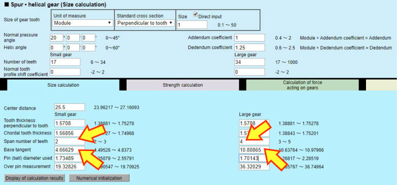
Figure 5-2 Span number of teeth and base tangent
c :
The tolerance of the base tangent becomes the backlash. A gap in meshing is made by reducing the thickness of teeth by the amount of the tolerance. The backlash value used to be determined in JIS B 1703:1976, but that standard has been abolished. Therefore, refer to the "Circumferential backlash" on the "Backlash conversion" tab of the gear calculation software. Tolerance of 0.05mm is used for the small and large gears to ensure the resulting backlash of 0.1mm. Furthermore, to not reduce the backlash any more, specify the tolerance in the direction of the thinner tooth width (Figure 5-3). (Please determine the value of the width by yourself)
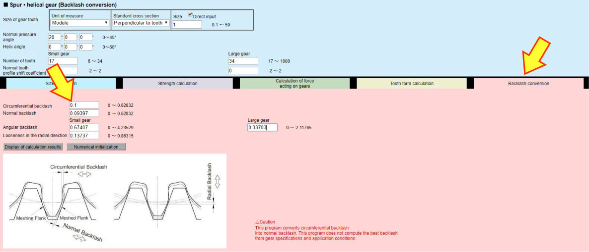
Figure 5-3 Setting the backlash
d :
The hardness resulting from a heat treatment depends in part on the material and may be HRC60 at the maximum. Please enter a value using catalogs as references.

" Tooth shape is represented by specification table, not projection drawing ! "
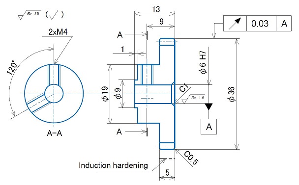
2. Execute the drawing of the large gear "2"
Draft in the same way as the small gear "1". (Figure 5-4)
| Spur gear | ||||
| Gear profile | Standard | Finishing method | Hobbing | |
| Tool | Profile | Standard full depth | Accuracy | JIS B 1702 Grade 4 |
| Module | 1.0 | Remark Number of teeth of mating gear: 17 Shift of mating gear: 0 Center distance: 25.5 Material / S45C Heat treatment / Induction hardening Hardness / HRC45-55 Surface treatment / Black oxide except tooth face |
||
| Pressure angle | 20° | |||
| Number of teeth | 34 | |||
| Pitch diameter | 34 | |||
| Profile shift coefficient | 0 | |||
| Total depth | 2.25 | |||
| Thickness | Base tangent length | 4.67 (-0.08/-0.18) | ||
| Span number of teeth | 4 | |||
Explanation of each item
Skipped as they are the same as the small gear.
3. Execute the drawing of the gear box "5"
Note that only the important dimensions related to function are displayed and other general dimensions are omitted. (Figure 5-5)
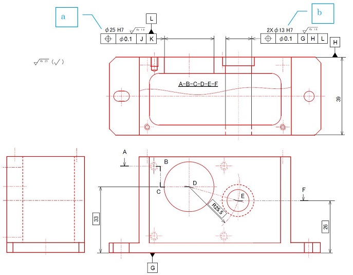
Figure 5-5 Example of a drawing of the gear box
Explanation of each item
a:
Determine the position of the hole for placing the motor. "Positional tolerance" of geometric tolerance regulates to ensure that the height of 33mm from the mounting surface for the gear box (datum G) and the hole is at right angle to the motor mounting surface (datum H). Geometric tolerance is determined considering height accuracy required by the datum B. This time, we set it to 0.1.
b:
To ensure meshing of gears, determine the distance between the motor positioning hole and the two bearing holes for the shaft of the large gear (shaft center distance). The height of 26mm from the mounting surface (datum G) and the distance of 25.5mm from the motor positioning hole (datum L) are regulated by the "positional tolerance" of geometric tolerance.
As for the geometric tolerance value, refer to "Looseness in the radial direction" of the "Backlash conversion" tab of the gear calculation software. As the looseness in the radial direction is 0.13mm, specify the value less than that. Considering the height accuracy required by datum B, this time we set it to 0.1 (as opposed to the theoretical value of±0.05). (Figure 5-6)
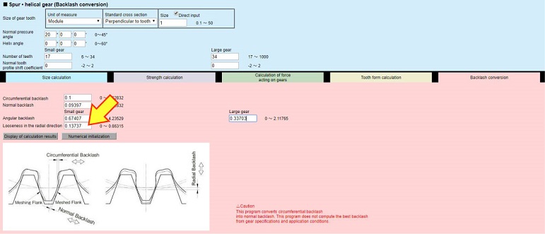
Figure 5-6 Tolerance of the shaft center distance

" We can use geometric tolerance for positioning ! "
We discussed how to execute the drawings of a pair of spur gears and a gear box.
This is the end of the fifth chapter of “Gear design procedure in practical design”. Thank you for reading !
*Illustration: KAOSUN
DISCLAIMER
The purpose of writing this article was to educate the readers with the elementary level of gear technology.
We hope that the actual design and manufacturing of gears and machinery utilizing gears are done with sufficient technical and specialized considerations under the user's full responsibility.
We disavow any liability and will not compensate for any direct or indirect damages caused by the gears designed by the users who read this article.