


1. Designing a gear’s basic shape (by hand calculation method)
Basic elements of gears temporarily determined in the previous chapter are shown below. (Table 2-1)
Table 2-1 Basic elements of gears determined temporarily| Basic element | Symbol | Shape and value |
|---|---|---|
| Gear type | - | spur gear |
| Module | m | 1.0 |
| Number of teeth of the small gear | Z1 | 17 |
| Number of teeth of the large gear | Z2 | 34 |
| Pressure angle | α | 20° |
Let’s see the processes to examine the shape of the gears from these basic elements.
1. Calculation of pitch circle diameter, d
The pitch circle diameter is calculated by using the basic elements shown above.
The pitch circle diameter of the small gear :
d1=m×Z1=1.0×17=17 (mm)
The pitch circle diameter of the large gear :
d2=m×Z2=1.0×34=34 (mm)
2. Calculation of the center distance, a
The center distance is also calculated by using the basic elements. The center distance is the distance between the shafts of a pair of gears.
The center distance :
a=(Z1+Z2)×m/2=(17+34)×1.0/2=25.5 (mm)
3. Calculation of the addendum length, ha, and the tooth depth, h
The addendum length of a general spur gear is obtained by the following formula. The addendum length is the length from the pitch circle diameter of the tooth shape to the top of the tooth :
ha=1×m=1×1.0=1 (mm)
The tooth length is obtained by the following formula. The tooth length is the length from the dedendum to the top of the tooth :
h=2.25×m=2.25×1.0=2.25 (mm)
4. The tip diameter, da, and the root diameter, df
The tip diameter of a spur gear is obtained by the following formula :
da1=d1+2m=17+(2×1.0)=19 (mm)
da2=d2+2m=34+(2×1.0)=36 (mm)
The root diameter of a spur gear is obtained by the following formula :
df1=d1-2.5m=17-(2.5×1.0)=14.5 (mm)
df2=d2-2.5m=34-(2.5×1.0)=31.5 (mm)
The parameters obtained by calculations are shown in the diagram below. (Figure 2-1)
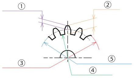
Figure 2-1 The meaning of each parameter
1. Addendum length, ha
2. Tooth length, h
3. Tip diameter, da
4. Root diameter, df
5. Pitch circle diameter, d
Here is the summary of the calculated results. (Table 2-2)
Table 2-2 Calculated results| Calculation items | Symbol | Formula | Calculated result (example) | |
|---|---|---|---|---|
| Small gear | Large gear | |||
| Module | m | - | 1 | |
| Tool pressure angle | α | - | 20° | |
| Number or teeth | Z1, Z2 | - | 17 | 34 |
| Center distance | a | (Z1+Z2)×m/2 | 25.5 | |
| Pitch circle diameter | d1, d2 | Z×m | 17.0 | 34.0 |
| Addendum length | ha1, ha2 | 1×m | 1.0 | 1.0 |
| Tooth length | h1, h2 | 2.25×m | 2.25 | 2.25 |
| Tip diameter | da1, da2 | d1+2m, d2+2×m | 19.0 | 36.0 |
| Root diameter | df1, df2 | d1-2.5m, d2-2.5×m | 14.5 | 31.5 |
The gears represented above mesh together as shown in the following diagram. (Figure 2-2)
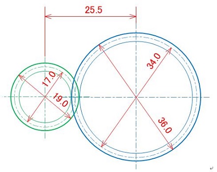
Figure 2-2 Basic structure of gears
2. Designing a gear’s basic shape (by gear calculation software method)
You may calculate in your head to get the previous values as these calculations are simple. Alternatively you can also calculate using a gear design software. Especially, miscalculations tend to occur in cases of helical gears or profile shifted spur gears. Therefore, we recommend that you use a gear calculation software.
Here, we will use “the KHK Free Gear Calculator” which can be done on the web.
We will show you below the steps of how to use the software.
1. Display the KHK Free Gear Calculator page
https://khkgears.net/new/gear_calculator.htmlAfter creating a new account, click the type of gears to calculate. (Figure 2-3)
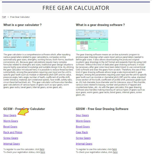
Figure 2-3 The top page of the KHK Free Gear Calculator
2. Display the page for size calculation
Move to the page for size calculation. (Figure 2-4)- Click "Size calculation" tab (Arrow A)
- Input module "Size" (Arrow B)
- Input "Number of teeth" of "the Small gear" (Arrow C)
- Input "Number of teeth" of "the Large gear" (Arrow D)
- Use default values for other items
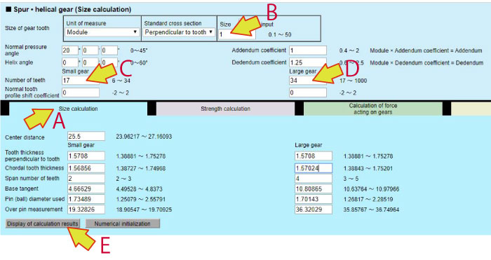
Figure 2-4 The page for size calculation
3. Display the calculation results
Click the button near the arrow E on Figure 2-4 to display the calculation results.
The values of elements that determine the gear’s shape are displayed on the list of results.(Table 2-3)

"What a useful software !
I don’t have to use a calculator !"
Table 2-3 The list of calculation results
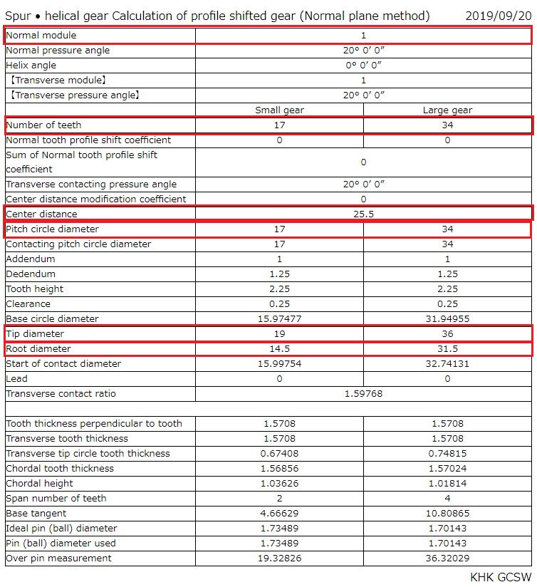
The list of the calculation results as shown above is displayed and can be saved as the design calculation.
In case of a later gear failure, you can verify the calculation process at the time of design using this design calculation record.
Next we will explain the strength calculation for the gears calculated in this chapter. (To be continued...)
*Illustration: KAOSUN
DISCLAIMER
The purpose of writing this article was to educate the readers with the elementary level of gear technology.
We hope that the actual design and manufacturing of gears and machinery utilizing gears are done with sufficient technical and specialized considerations under the user's full responsibility.
We disavow any liability and will not compensate for any direct or indirect damages caused by the gears designed by the users who read this article.