


- TOP >
- Gear Knowledge >
- Gear design procedure in practical design >
- Design of peripheral structures of gears
Example of a design approach for peripheral structures of gears
This time we check the process to design peripheral structures using the basic elements of the gears we designed in the previous chapter.
However, this process is just one example and there are more than one right answers for the design.
Design processes may vary according to the design concept of each design engineer.
1. Connecting a small gear "1" to a motor
Connecting a motor shaft and a small gear with set screws.(Figure 4-1)
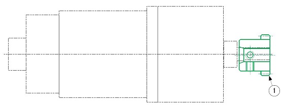
Figure 4-1 Connecting a motor and a small gear

"First consider the structure which connects the input side gear to a motor !"
2. Mesh a small gear and a large gear
Mesh a small gear "1" and a large gear "2". Use set screws for the large gear so that the gear can be installed to the shaft later. (Figure 4-2)
Use M4 screws for set screws (size referenced in the gear catalog).
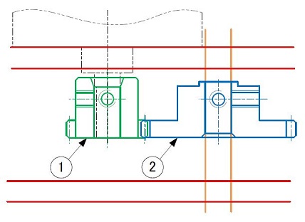
Figure 4-2 Meshing the small gear and the large gear
3. Arrange shaft and bearings to support the large gear
Temporarily assembly bearings "4" and a shaft "3" which support the large gear. Then, we can see that the bearing flange interferes with the motor flange as shown with a red arrow. (Figure 4-3)
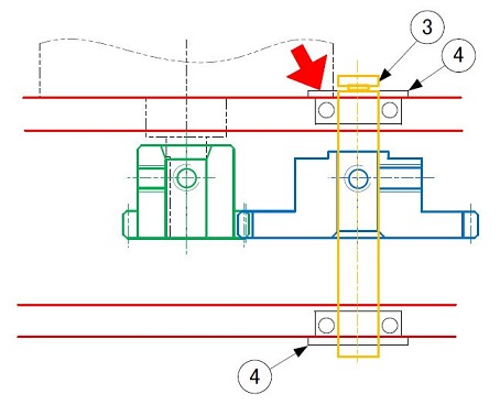
Figure 4-3 Bearing structure of the large gear (1)
You can take any of the following approaches to avoid this interference:
- Extend the distance between shafts of gears a little - you need to change the module or the number of teeth to expand the pitch circle diameters of gears
- Cut the interfering part of the motor flange - as the motor is purchased, this additional processing is not practical
- Embed the bearing flange of the interfering part by countersinking - possible to eliminate interference by additional processing of the side of the gear box
This time, we will decide to avoid the interference by countersinking the bearing flange. (Figure 4-4)
* Countersinking is the process to cut the face of the hole a little deeper with a larger diameter.
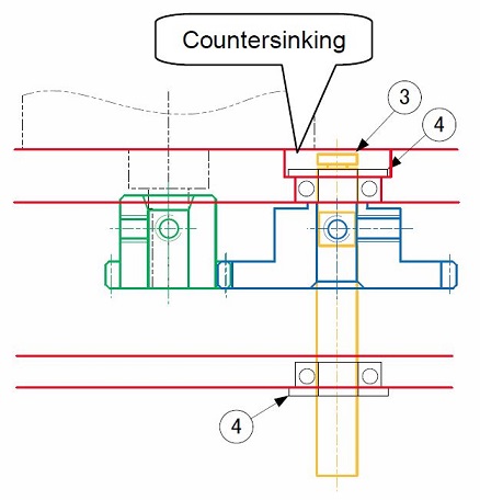
Figure 4-4 Bearing structure of the large gear (2)

"Understanding the relationship between input and output sides makes design easier !"
4. Design the gear box surrounding a pair of gears
Now we will design the shape of the gear box "5" that surrounds a pair of gears.
There is a premise to design a simple sealed structure, so that we assume the design to be a milled aluminum block. (Figure 4-5)
Assemble the motor and the small gear "1" in advance and make a small hole (diameter D) in the box "5" larger than the outer diameter of the small gear so that the assembly can be inserted.
Set screws of the large gear "2" can be tightened with a hexagonal wrench without any problem.
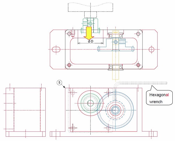
Figure 4-5 Example of a gear box shape design
5. Design other parts
A coupling is mounted at the tip of the shaft of the large gear in order to link rotative power.
Add a spacer "6" for alignment to the shaft that supports the large gear, and add a cover "7" to the gear box. (Figure 4-6)
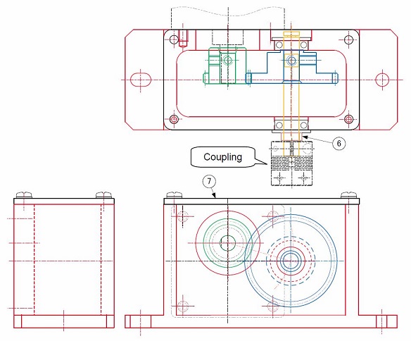
Figure 4-6 Design of other parts
The assembly position of the small gear "1" is determined by the face of the tip of the motor shaft.
There is a space of several millimeters between the edge surface of the tooth thickness (the hub side of the tooth) and the set screws as shown in the pale yellow areas outlined with red lines, so that the tooth width can be widened on the hub side. (Figure 4-7)
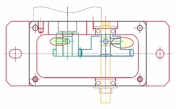
Figure 4-7 Utilizing dead space
4mm is enough for a tooth width to achieve the target strength for this machine, but the design can be utilized for other machines in the future if the tooth width is widened a little more. Therefore, we will increase the tooth width to 5mm. (Figure 4-8)
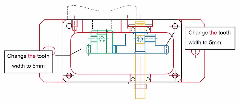
Figure 4-8 Changing (widening) tooth width
This time we illustrated an example of how to design peripheral parts of a pair of spur gears.
Next, we will explain the drawings of the main parts we designed in this chapter. (To be continued...)
*Illustration: KAOSUN
DISCLAIMER
The purpose of writing this article was to educate the readers with the elementary level of gear technology.
We hope that the actual design and manufacturing of gears and machinery utilizing gears are done with sufficient technical and specialized considerations under the user's full responsibility.
We disavow any liability and will not compensate for any direct or indirect damages caused by the gears designed by the users who read this article.