


- TOP >
- Gear Knowledge >
- Gear design procedure in practical design >
- Clarify specifications and determine basic elements
Introduction
Many mechanical products around you use gears that guarantee function. Machine design engineers should be good at gear design because gears are used in most mechatronics products which incorporate motions. However, in reality there are only a few engineers who can design gears by calculation by themselves.
How can they develop products without being able to design gears?
Maybe they make do with the following two methods.
- Divert gear design from other machines which have similar numbers of teeth, shapes, and sizes
- Choose ready-made products from catalogs of gear manufacturers
The above-mentioned methods are not always wrong, but they might be choosing gears considering only the number of rotations and spaces without calculating strength. Such designs must eventually lead to failures which could result in damage to life and property.
In this series, we explain how to design gears and peripheral parts according to procedures using simple mechanisms.
1. Clarify specifications
Design input is necessary when considering a mechanism. Design input is the product specification. There are two requirements for design when considering a gear mechanism.
- Requirement for torque of output shaft to satisfy specifications
- Requirement for the number of rotations of output shaft to satisfy specifications
In general, any torque value can be used with no trouble as long as it exceeds the envisaged value.
However, the number of rotations often influences performance to satisfy product specifications and processing speed. Therefore, in many cases, the number of rotations is adjusted while guaranteeing torque when designing.
However, the exact number of rotations of DC motors cannot be obtained because the number of rotations of DC motors vary with load. When an accurate number of rotations is required, use sensors to control the number of rotations or use stepping motors.
" First of all, specifications are most important ! "

2.Envisage transmission of rotation layout
At first, let’s consider several layout structures to transmit rotation. You need to compare the structures to choose the most suitable one taking into account not only gears but also liability and cost by combining various machine elements.
[Conditions]
- Output axis requires rotational torque of ≥600N·mm (0.6N·m) and the number of rotations of about 15rpm
- Use a commercial DC geared motor whose rated torque is 390N·mm (0.39N·m) and rated rotational speed of 30rpm as a power source.
- Use a simple closing type box to prevent dust or foreign material from infiltrating into the mechanism part
- Aim for ease of assembly, miniaturization and cost reduction
To satisfy the conditions, consider a gear transmission mechanism and a belt transmission mechanism as the machine elements to transmit rotation continuously.(Table 1-1)
The comparative chart in the next page is just a sample. When you actually design, you need to list several possible structures to compare liability, ease of assembly, and cost in detail to make a comprehensive judgment.
According to "1" and "2" in the above-mentioned conditions, when speed reduction ratio is 2, it is judged that you can satisfy 15rpm (half of motor’s rated rotation speed) as well as the torque requirment.
| Gear transmission mechanism | Belt transmission mechanism | |
| Mechanism | 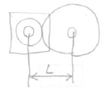 |
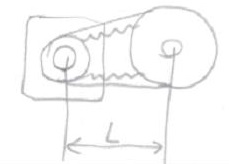 |
| Specification | Required torque and the number of rotations are satisfied by setting gear ratio to 2 to reduce speed. | Required torque and the number of rotations are satisfied by setting pulley ratio to 2 to reduce speed. |
| Space | Distance L can be reduced more than belt transmission mechanism. | As the gap between pulleys is needed to avoid interference, distance L is larger than the gear transmission mechanism. |
| Ease of Assembly | Assembling gears in the sealed structure is easy. | Installing a belt in the sealed structure is difficult. |
| Cost | Two driving parts (small gear, large gear) | Three driving parts (small pulley, large pulley, belt) |
| Result | Good | Fair |
According to the above result, we will design the reducer with gears.
3. Temporarily determining a gear’s elements
You need to consider the following items to design gears.
- Module: influences gear diameter as well as gear strength
- The number of teeth: influences gear diameter as well as speed ratio
- Helix of gears: decide whether spur gears or helical gears are needed to make a comprehensive judgement considering strength, noise, distance between shafts, and machine efficiency
The pitch circle diameter is decided by multiplying module by the number of teeth which also decides the space gears occupy which then partly determines the size of the gear box.
1. Temporarily determining a gear’s shape (helical or not)
As there is no particular reason to choose helical gears, we use commonly-used spur gears without a helix because calculation is easy and machine efficiency η of about 99% is expected even considering the mechanical loss in the bearings.
Helical gears may be chosen if noise reduction of meshing gears is included in the design condition.
2. Temporarily determining the number of teeth
Use a motor that has the rated torque of 390N·mm (0.39N·m) and rated rotational speed of 30rpm.
As required, the number of rotations of the output shaft is 15rpm and the torque is ≥600N·mm (0.6N·m). You can satisfy both requirements if the gear ratio is 2.
You need to reduce the size of the small gear as much as possible to minimize the size of the unit.
When designing using standard gears, temporarily determine the small gear's number of teeth to be Z1=17 which avoids the need for profile shifted gears. Then, the large gear's number of teeth Z2=34 is determined.
If space is tight, the small gear's number of teeth may be reduced to Z1=14.
3. Temporarily determining module
A design engineer who is used to gear design might be able to determine the module instinctively based on his or her experience.
However, the designer who is inexperienced in gear design may have no idea which module is suitable.
In this case, you can refer to the module in the catalog of gear manufacturers whose allowable torque is larger than the load torque.
Based on specifications, the load torque of the output shaft is expressed by the following formula.
The motor's rated torque 390N·mm (0.39N·m) × (speed reduction ratio 2) × (machine efficiency) = 772.2N·mm(0.772N·m).
As impact load may be applied due to an unexpected sudden system shutdown, the safety factor is set to 1.5.
Therefore, the load torques on the small gear and the large gear are calculated as follows:
Small gear: 390.0N·mm (0.390N·m) × 1.5 = 585N·mm (0.585N·m)
Large gear: 772.2N·mm (0.7722N·m) × 1.5 = 1158.3N·mm (1.1583N·m)
Let us check from the catalog "the allowable bending strength" and "the allowable tooth surface strength" when this torque is applied.
The allowable torques are excerpted for the non-heat treated SS series spur gears in the KHK master catalog. (Table 1-2)
[Conditions] Number of teeth 17: ≥585N·mm (0.585N·m), Number of teeth 34: ≥1158.3N·mm (1.1583N·m)
| Module | Number of teeth | Allowable torque (N·m) | Catalog Part No. (reference) | Decision | |
| Bending strength | Tooth surface strength | ||||
| 0.5 | 17 | 0.56 X | 0.028 X | SS0.5-17 | X |
| 34 | 1.50 O | 0.12 X | SS0.5-34 | ||
| 0.8 | 17 | 2.30 O | 0.12 X | SS0.8-17 | X |
| 34 | 6.13 O | 0.50 X | SS0.8-34 | ||
| 1.0 | 17 | 4.50 O | 0.23 X | SS1-17 | X |
| 34 | 12.0 O | 1.03 X | SS1-34 | ||
| 1.5 | 17 | 15.2 O | 0.80 O | SS1.5-17 | O |
| 34 | 40.4 O | 3.63 O | SS1.5-34 | ||
According to Table 1-2, while allowable bending stress (resistance against tooth breakage) increases as the module becomes larger, tooth surface strength (resistance against peeling or such) doesn’t increase in proportion to the module.
The reason why the tooth surface strength doesn’t increase is assumed to be because the SS series uses untempered raw material.
" Even if bending strength is OK, surface strength might not be enough. Be careful ! "

Then, let us look at the tempered MSGA and KSG series. (Table 1-3)
As the number of teeth 17 and 34 are not in the catalog, we use values close to them instead.
[Conditions] Number of teeth 17: ≥585N·mm (0.585N·m), Number of teeth 34: ≥1158.3N·mm (1.1583N·m)
| Module | Number of teeth | Allowable torque (N·m) | Catalog Part No. (reference) | Decision | |
| Bending strength | Tooth surface strength | ||||
| 1.0 | (18) | 12.1 O | 6.37 O | KSGA1-18 | O |
| (35) | 30.7 O | 26.2 O | KSGA1-35 | ||
| 1.0 | (20) | 10.3 O | 5.48 O | KSG1-20 | O |
| (32) | 19.1 O | 16.2 O | KSG1-32 | ||
We discover that the tooth surface strength becomes large enough by heat treatment.
If you try to choose gears that satisfy specifications simply from a catalog, the following problems may occur.
- When using an inexpensive gear without the heat treatment, the tooth surface strength may not be enough and you have to choose a gear with a larger module.
- As for heat-treated and polished expensive gears, choices of the number of teeth and modules are limited, so you may be forced to choose a high-cost gear with over-specification.
- As for MSGA and KSG series, chromium/molybdenum material (SCM415+carburizing and quenching, SCM440+induction hardening) is heat-treated and tooth surface is polished, therefore tooth surface strength exceeds requirement.
Further consideration indicates…
- Based on Table 1-2, module of ≥1.5 is needed in view of allowable bending strength.
- Based on Table 1-3, tooth surface strength improves by heat treating, and module of 1.0 is enough.
As a result, with the consideration of cost, we decide to use S45C material after heat treating which has less hardenability but is cheaper than chromium/molybdenum material.
Therefore, the module is temporarily determined as 1.0 at this time.
4. Temporarily determining pressure angle
This element determines inclination of tooth profile and 20° is generally used. So, we will use 20°.
We temporarily determined parameters when designing gears by ourselves in this chapter.
In the next chapter, we will explain the process to design the gear shape. (To be continued…)
*Illustration: KAOSUN
DISCLAIMER
The purpose of writing this article was to educate the readers with the elementary level of gear technology.
We hope that the actual design and manufacturing of gears and machinery utilizing gears are done with sufficient technical and specialized considerations under the user's full responsibility.
We disavow any liability and will not compensate for any direct or indirect damages caused by the gears designed by the users who read this article.