


We finished the gear’s shape in the previous chapter.
However, we have to confirm if this gear guarantees strength before use.
This time we will explain the process of strength calculation.
The strength calculation of a tooth includes "tooth bending strength" and "tooth surface strength" and both need to be satisfied.
1. Calculation of tooth bending strength
The tooth bending strength is calculated as follows. σF means the bending strength applied to the dedendum.
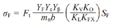
As you can see in the formula above, there are various parameters and some of them are implicitly determined. However if you have no experience in designing gears, you can’t do the calculation as you don’t know these implicitly determined values.
In addition, there are the potentials for loss of time or calculation error. Therefore, it is best to use a gear calculation software.
Here we use "KHK Free Gear Calculator" which can be used on the web.
1. Display the KHK Free Gear Calculator page
https://khkgears.net/new/gear_calculator.htmland click on the type of gears to calculate. (Figure 3-1)

Figure 3-1 Top page of KHK Free Gear Calculator
2. Display the page for strength calculation
Move to the page for strength calculation (bending strength). (Figure 3-2)- Click the "Strength calculation" tab. (Arrow A)
- Press the "Calculation of bending strength" button. (Arrow B)
- Choose (N) in the "Unit of force" box. (Arrow C)
- Temporarily input "5mm" for each tooth width. (Arrow D)
* The tooth width is the thickness of teeth in depth - Set the "Gear material" (Arrow E) to S45C.
- Input 30 for the "Rotational speed (rpm)". (Arrow G)
- We use the default setting values for other parameters at this time.
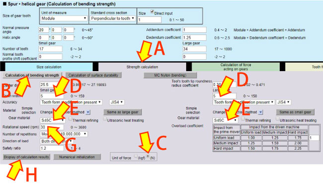
Figure 3-2 Page for strength calculation (bending strength)
3. Display the bending strength calculation results
Click Arrow H in Figure 3-2 to display the result of the bending strength calculation. (Table 3-1)
It will be judged that the bending strength of both gears satisfy the required strength if the allowable torque of each gear exceeds the load torque.
Reference : Load Torque (See Clarify specifications and determine basic elements)
Small gear...585N·mm (0.585N·m) or more
Large gear...1158.3N·mm (1.1583N·m) or more
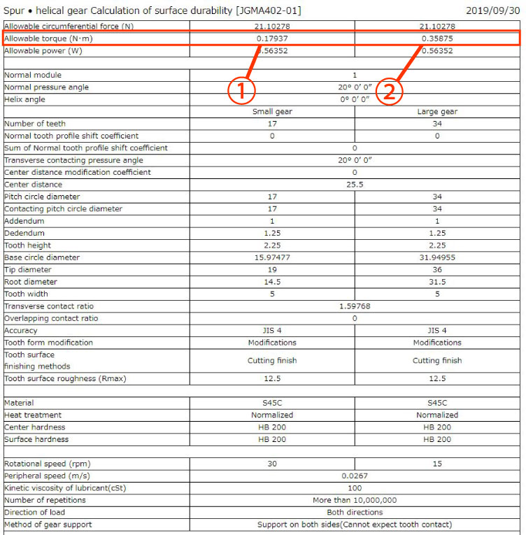
Table 3-1 Calculation results of the bending strength of the tooth
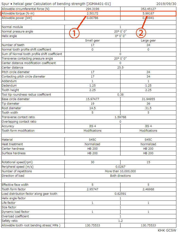
1. This value is acceptable as allowable torque is more than 0.585N·m
2. This value is acceptable as allowable torque is more than 1.1583N·m
2. Calculation of tooth surface strength
1. Display the calculation results of the tooth surface strength
After checking the tooth bending strength, we will confirm the tooth surface strength. (Figure 3-3)i) Click "Calculation of surface durability". (Arrow A)
ii) Click "Display of calculation results" button. (Arrow B)
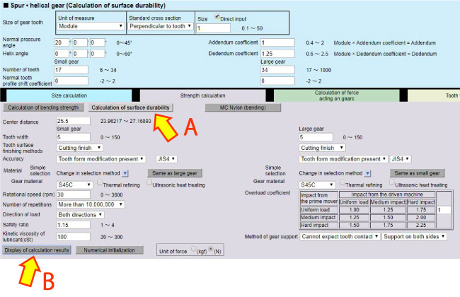
Figure 3-3 Page for strength calculation (surface strength)
2. Display the surface strength calculation results
Click Arrow B in Figure 3-3 to display the results of the surface strength calculation. (Table 3-5)
It will be judged that the surface strength of both gears satisfies the required strength if the allowable torque of each gear exceeds the load torque.
Reference : Load Torque (See Clarify specifications and determine basic elements)
Small gear...585N·mm (0.585N·m) or more
Large gear...1158.3N·mm (1.1583N·m) or more
You can see that the surface strengths of the teeth of small gear and large gear are unsatisfactory from Table 3-2.
Therefore, some basic element needs to be changed.
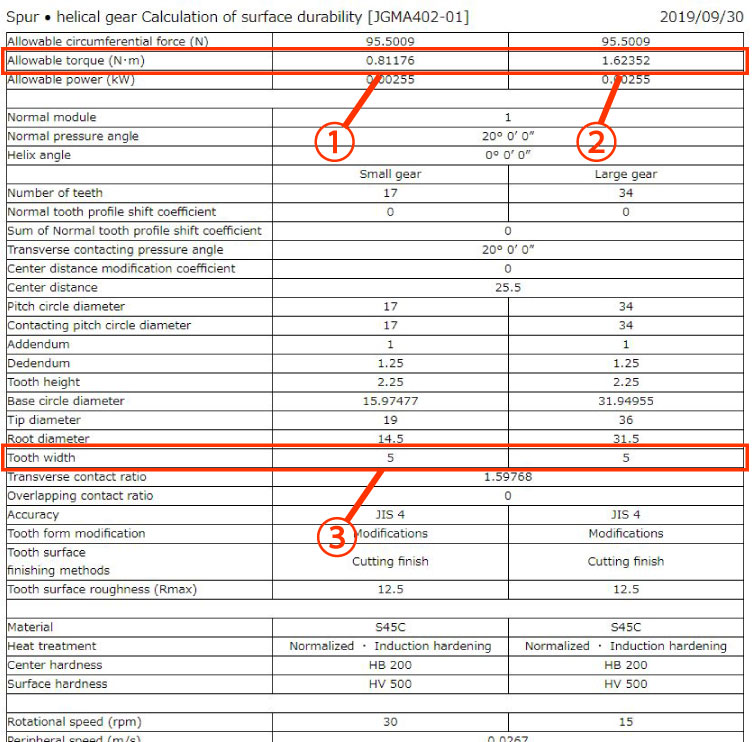
Table 3-2 Calculation results of the surface strength of the tooth (1st try)
1. This value is unacceptable as allowable torque is less than 0.585N·m
2. This value is unacceptable as allowable torque is less than 1.1583N·m
3. Change parameters to correct the deficiency of the tooth surface strength
Now we can see that neither the small gear nor the large gear guarantee tooth surface strength.
Now, we try broadening the tooth width to lower the surface pressure on the tooth.
As you change the tooth width, you will see that 22mm is enough to satisfy the necessary tooth surface strength. (Figure 3-4)
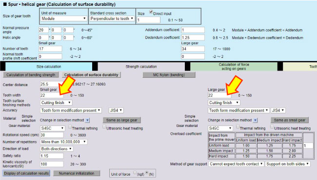
Figure 3-4 Tooth width change
Table 3-3 Calculation results of the surface strength of the tooth (2nd try)
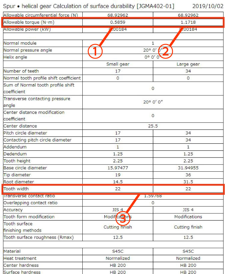
1. This value is acceptable as allowable torque is more than 0.585N·m
2. This value is acceptable as allowable torque is more than 1.1583N·m
3. Tooth width is broadened to 22mm
By widening the tooth width to 22mm, the surface pressure is lowered and the necessary tooth surface strength is satisfied.
However, broadening the tooth width may lead to needing a larger machine, and rise in the part’s price due to the increase in time necessary to cut the gear.
So now, we will consider increasing the hardness of the tooth surface to satisfy the necessary tooth surface strength without widening the tooth width.
4. Change parameters to correct the deficiency of the tooth surface strength
Return tooth width to 5mm and add induction hardening to the tooth surface. (Figure 3-5)
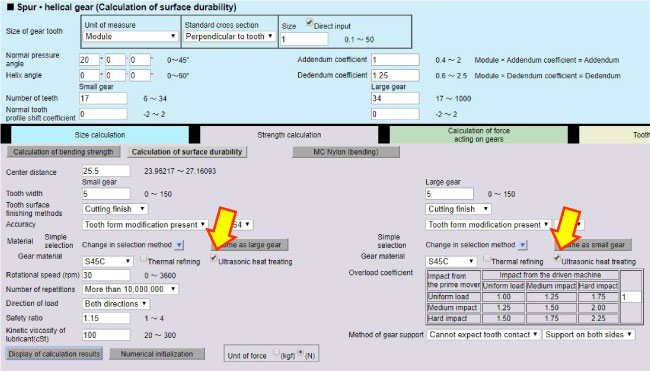
Figure 3-5 Addition of induction hardening
Table 3-4 Calculation results of the surface strength of the tooth (3rd try)
1. This value is acceptable as allowable torque is more than 0.585N·m
2. This value is acceptable as allowable torque is more than 1.1583N·m
3. Tooth width returns to 5mm
5. Change parameters to correct the deficiency of the tooth surface strength
Now we can see that the necessary tooth surface strength is satisfied by induction hardening even when the tooth width is reduced back to 5mm.
We will try to decrease tooth width a little more since the allowable torque has plenty of capacity for the load torque.
The tooth thickness was temporarily set to 5mm, and we will now make the tooth thinner.
As we decrease the tooth thickness by 1mm and re-calculate the tooth surface strength, we find the necessary tooth surface strength is still satisfied when the thickness of the small gear and the large gear are decreased to 4mm. (Figure 3-6)
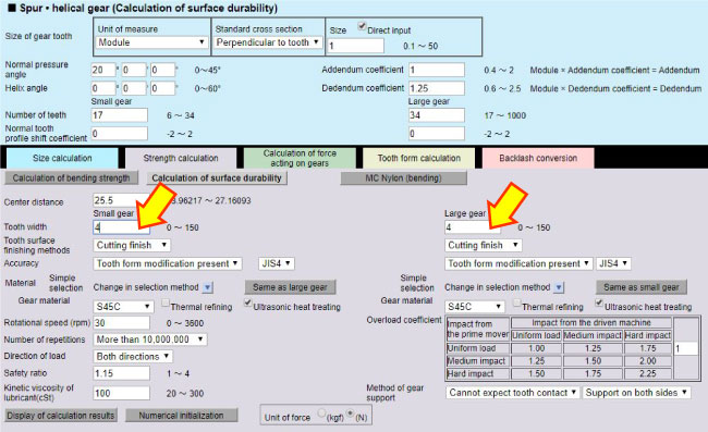
Figure 3-6 Change of tooth thickness
6. Recalculation of the tooth surface strength
Check calculation result in Table 3-5.
Reference : Load Torque (See Clarify specifications and determine basic elements)
Small gear...585N·mm (0.585N·m) or more
Large gear...1158.3N·mm (1.1583N·m) or more
You can see from Table 3-5 that the tooth surface strength is satisfactory even when the tooth width is 4mm.
Table 3-5 Calculation results of the surface strength of the tooth (4th try)
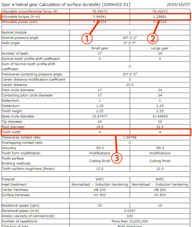
1. This value is acceptable as allowable torque is more than 0.585N·m
2. This value is acceptable as allowable torque is more than 1.1583N·m
3. Tooth width is decreased to 4mm
Calculate the tooth bending strength again with the 4mm tooth width. (Table 3-6)
Table 3-6 Tooth bending strength calculation results
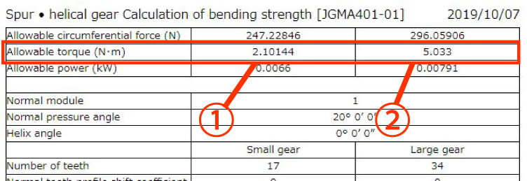
1. This value is acceptable as allowable torque is more than 0.585N·m
2. This value is acceptable as allowable torque is more than 1.1583N·m
As a result of the calculations, we can now see that the necessary bending strength and the surface strength of the tooth are satisfied if the tooth thickness is 4mm.
Therefore, we design with a tooth width of 4mm or more.
The tooth shape will be as shown below. (Figure 3-7)
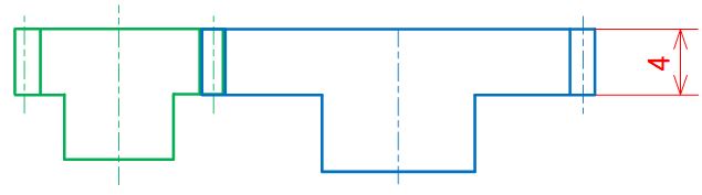
Figure 3-7 Image of the tooth shapes
If the tooth strength is insufficient, you can adjust it by changing the hardness and/or the tooth thickness without re-setting the module again.
As you saw in the above examples, the calculation results are displayed and you can save them as the design calculation.
In case of a gear failure, you can check the calculation process at the time of design using this design calculation.
Next we will explain how to design peripheral structures with the gears we calculated.
(To be continued...)
*Illustration: KAOSUN
DISCLAIMER
The purpose of writing this article was to educate the readers with the elementary level of gear technology.
We hope that the actual design and manufacturing of gears and machinery utilizing gears are done with sufficient technical and specialized considerations under the user's full responsibility.
We disavow any liability and will not compensate for any direct or indirect damages caused by the gears designed by the users who read this article.