


1. Gear Types and Characteristics
In the following pages we present three general gear categories corresponding to KHK Stock Gear Classifications.
Categories of Gears – Parallel Axis Gears
Types of Gears : Spur Gear

Efficiency (%) – 98.0−99.5
KHK Stock Gears – MSGA, SSG, SS, SUS, PS
Types of Gears : Helical Gear
Efficiency (%) – 98.0−99.5
KHK Stock Gears – KHG, SH
Types of Gears : Rack and helical rack
Efficiency (%) – 98.0−99.5
KHK Stock Gears – KRG(F)(D), SRFD, SUR(F)(D), PR(F), KRHG(F)
Types of Gears : Internal Gear
Efficiency (%) – 98.0−99.5
KHK Stock Gears – SI, SIR
Categories of Gears – Intersecting Axis Gears
Types of Gears : Miter Gear
Efficiency (%) – 98.0−99.0
KHK Stock Gears – MMSG, SMSG, MM, SUM, PM
Types of Gears : Straight Bevel Gear
Efficiency (%) – 98.0−99.0
KHK Stock Gears – SB and SBY, SB, SUB, PB, DB
Types of Gears : Spiral Bevel Gear
Efficiency (%) – 98.0−99.0
KHK Stock Gears – MBSG, SBSG, MBSA(B), SBS
Categories of Gears – Nonparallel and Nonintersecting Axis Gears
Types of Gears : Screw Gear (Crossed Helical Gear)
Efficiency (%) – 70.0−95.0
KHK Stock Gears – SN, SUN, AN, PN
Types of Gears : Worm and Worm Wheel

Efficiency (%) – 30.0−90.0
KHK Stock Gears – KWGDL(S) & AGDL, KWG & AGF, SWG & AG, SW & BG and CG, SW & PG
Gear types are classified into 3 categories, generally by the directions of the mounting shafts. Here, in this section, we introduce the characteristics of gears, how to use gears, and technical tips (hints).
1-1 Parallel Axes Gears
Gears involving two axis, which are parallel to each other, are called Parallel Axis Gears. For the transmission of rotation/power by parallel axis, Spur, Helical and Internal Gears are generally used. These are the most commonly used gears, with a wide range of applications, in various industries.
Spur Gear
A spur gear is a cylindrical shaped gear, in which the teeth are parallel to the axis. It is the most commonly used gear with a wide range of applications and is the easiest to manufacture.
Characteristics / Technical Hints :
– A gear which is the most easiest to manufacture.
– A gear that is easy to use and does not produce axial thrust forces.
– There is no limit in the combination of the number of gear teeth of paired gears.
Speed Ratio :
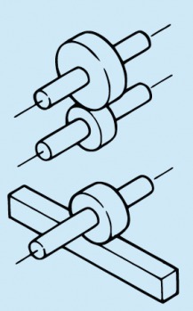
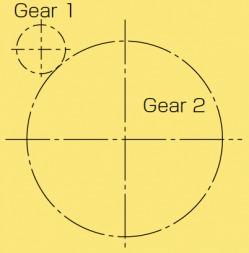
In Figure.1.1, a pair of meshed gears in single-stage gear train. As you can see, the rotational direction of the paired gears is opposite to each other. If Gear 1 rotates clockwise, then Gear 2 rotates counterclockwise. Also, if paired gears have a different number of teeth, the speed will be increased / decreased; If Gear 1 is a drive gear, speed is reduced. If Gear 2 is a drive gear, speed is increased.
Speed Ratio
= Number of teeth of driven gear (z2) / Number of teeth of drive gear (z = 1)
= Rotation of drive gear (n1) / Rotation of driven gear (n2)
(1.1)
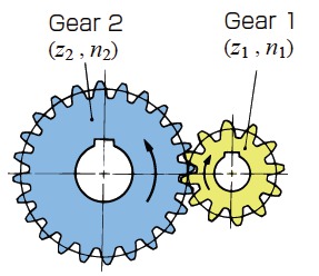
Fig 1.1 Spur Gear
Calculation Example :
Number of teeth of drive Gear1 : 20
Rotation of gear : 400rpm
Number of teeth of driven Gear2 : 80, Single-stage gear train.
The Speed ratio of this gear train : 80÷20=4
The rotation of Gear2 : 400÷4=100rpm
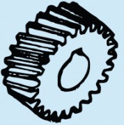
Helical Gear
The spur gear that has helix teeth (helicoids teeth) is called Helical Gear. Helical gears can bear load more than spur gears and work more quietly. They are also widely used in different industries, such as the automotive, and in industrial machinery.
Characteristics and Technical Hints :
– More strength than the spur gear of the same size; transmits rotational force / power quietly.
– Suitable for use in high speed rotations.
– Produces axial thrust force, need to cope with these extra forces
– There is no limit in the combination of number of gear teeth of paired gears.
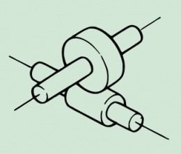
The direction of the rotation and the thrust force in meshed helical gears are illustrated in the Figure 1.2. Thrust bearing receives thrust force. The direction of the rotation is the same as meshed spur gears.
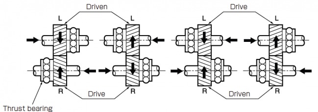
Fig 1.2 Direction of Rotation and Thrust Force
(Important Gear Terminology and Gear Nomenclature in Fig 1.2)
- Thrust bearing
A paired gear rotates in opposite direction each other. The speed ratio is the same as it for spur gears.
Speed Ratio of Two-Stage Gear Trains :
If Gear 1 is a drive gear, the speed ratio (i) for this two stage gear train is calculated as below.
Speed ratio (i)
= z2 / z1 x z4 / z3
= n1 / n2 x n3 / n4
(1.3)
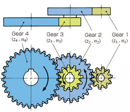
Fig 1.3 Two-Stage Gear Train
Gear 1 and Gear 4 rotate in the same direction. Number of teeth of Gear 1/2/3/4 is 10/24/12/30, respectively, then, the reduction ratio for this gear train is 6.
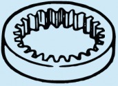
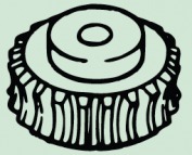
Internal Gear
This is a cylindrical shaped gear, but with teeth inside the circular ring, and can mesh with a spur gear. Internal gears are often used in Planetary Gear Systems, or Gear Couplings.
Characteristics / Technical Hints :
– Involves more complexity in manufacturing compared, to spur gears.
– By using planetary gear systems, it enables you to create a compact gear system applicable for high reduction ratio.
– For a pair of internal and external gears meshed, the following 3 interferences might occur :
(a) Involute Interference (b) Trochoid Interference (c) Trimming Interference
– No limit to the combination of the number of gear teeth, of paired gears.
Speed Ratio :
In the simplest example of a meshing External Gear 1 (Pinion) with an Internal Gear 2, both the External Gear 1 and Internal Gear 2 rotate in the same direction, as shown in Fig, 1.4
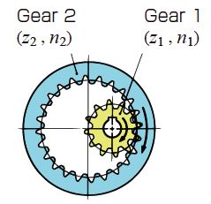
Fig.1.4 Spur Gear and Internal Gear
Speed Ratio
= Number of teeth of Driven Gear / Number of teeth of Drive Gear
(1.3)
Planetary Gear Systems :
Planetary Gear System consists of 4 major elements ;
Sun Gear (A), Planet Gear (B), Internal Gear (C), and Carrier (D)
In the system shown in Fig. 1.5, 4 planet gears are used.
The load division shared by many gears enables a compact system. The speed ratio or the direction of rotation in the Planet Gear System differs, depending on what factor is fixed.
(a) Planetary Type
If the Sun gear is of input, and the Carrier gear is of output, and the Internal gear is fixed ;
Speed Ratio
= Zc / Za + 1
(1.4)
(b) Solar Type
Sun Gear is fixed.
(c) Star Type
Carrier Gear is fixed.
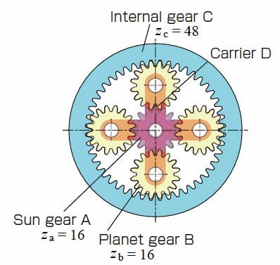
Fig.1.5 Example of a planetary gear system
(Important Gear Terminology and Gear Nomenclature in Fig 1.5)
- A Sun gear
- B Planet gear
- C Internal gear
- D Carrier
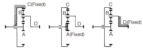
Fig.1.6 Planetary Gear Mechanism
Left – Planetary type / Center – Solar type / Right – Star type
1-2 Gears with Linear Motion
Gears with Linear Motion are classified as Parallel Axis Gears, but there are specific types of “Linear Motion” that involve no mating shafts. To convert rotational movement to linear motion, or the converse, Racks and Pinions are used in combination. Cylindrical shaped gears with an infinite radius are called Racks, generally used in conveyors.
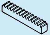
Spur Rack
This is a linear shaped gear, which has a straight-line tooth profile and can mesh with a spur gear. The spur rack can be regarded as a portion of a spur gear with an infinite radius, and several racks can combined in a line.
Characteristics / Technical Hints :
– Easier to manufacture and to use than helical racks.
– Can mesh with a spur gear with any number of teeth.
In regards to a meshed rack and pinion, the movement distance when the pinion rotates one time, is calculated from the number of teeth multiplied by the pitch. Pitch denotes the distance between corresponding points on adjacent teeth. CP racks are designed for easy positioning. ( Figure 1.7 )
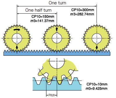
Fig.1.7 Difference between CP10 and m3
Movement of one cycle of the CP10-30 pinion on a CP rack vs.SS3-30 (m3) on a m3 rack.
Helical Rack
This is a linear shaped gear that meshes with a helical gear. A helical rack can be regarded as a portion of a helical gear with infinite radius.
Characteristics / Technical Hints :
– Produces thrust force; coping mechanism must be considered
– Rotates and transmits power more quietly than a helical rack of the same size
– Suitable for use in high speed rotation
– Can mesh with a helical gear with any number of teeth
It produces thrust force due to the gear-tooth helix. The Figure 1.8 shows the direction of rotation and the thrust force.
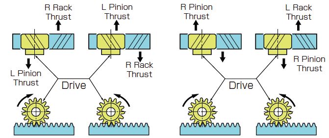
Fig.1.8 Direction of Rotation and Thrust Force
(Important Gear Terminology and Gear Nomenclature in Fig 1.8)
- Rack thrust
- Pinion thrust
1-3 Intersecting Axis Gears
Gears involving two axis crossing at a point are called Intersecting Axis Gears; general applications include rotation / power transmission of Bevel gears. Bevel Gears with gear ratio of 1, are called Miter gears. Bevel Gears are classified as Straight-Bevel Gears or Spiral-Bevel Gears, depending on the tooth form.
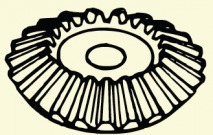
Straight Bevel Gear
This is a gear in which the teeth have tapered conical elements that have the same direction as the pitch cone base line (generatrix). The straight bevel gear is both the simplest to produce and the most widely applied in the bevel gear family.
Characteristics / Technical Hints :
– Easier to manufacture than Spiral Bevel Gears.
– Ease of use, produces no thrust force in the negative direction.
– The combination of the Number of teeth of paired gears is important. Those gears produced in combination do not mesh with other bevel gears.
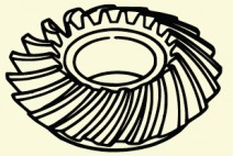
Spiral Bevel Gear
A bevel gear that has spiral teeth with a helical angle, which is more complex to manufacture, but offers advantages of higher strength and less noise.
Characteristics / Technical Hints :
– Suitable for use in high load / rotation. Better than Straight Bevel Gears
– Axial thrust force should be carefully considered
– Transmits rotational force / power more quietly than Straight Bevel Gears.
– Since these gears are produced as a pair, in accordance with the number of teeth, they do not mesh with other gears, even if they have the same modules or pressure angles.
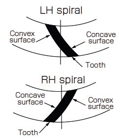
Fig.1.10 Contact Surface of Spiral Bevel Gears
(Important Gear Terminology and Gear Nomenclature in Fig 1.10)
- Concave surface
- Convex surface
Speed Ratio :
Speed Ratio
= Number of teeth of Driven Gear / Number of teeth of Drive Gear
(1.5)
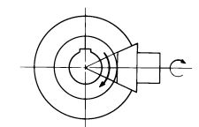
Thrust force on Spiral Bevel Gear :
The figure on the right shows the rotational direction and thrust force for the mesh of spiral bevel gears, with gear ratio more than 1.57. If the pinion meshes with a convex tooth-face, it produces thrust force in the negative direction.
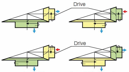
Fig.1.11 Direction of Rotation and Thrust Force
Green:RH / Yellow:LH / Blue: Positive Thrust Force / Red: Negative Thrust Force
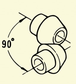
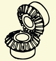
Straight & Spiral Miter Gear
Gears which are used as a pair, with the same number of teeth, are called Miter Gears. There are two types of miter gears; a miter gear of straight bevel gears, and the other is a miter gear of spiral bevel gears. Generally, they have a shaft angle of 90 degrees, however, KHK offers standardized angular miter gears with the shaft angle at 45, 60, and 120 degrees.
Characteristics / Technical Hints :
– Bevel gears with the gear ratio at 1 is deemed a Miter Gear
– Used for changing rotational or axial directions
Thrust Force on Spiral Miter Gears :
The Figure 1.12 shows the rotational direction and the thrust force on spiral miter gears. In case they produce thrust force in a negative direction as well as in a positive direction, the bearings must be positioned carefully so they can receive the forces evenly.

Fig.1.12 Direction of Rotation and Thrust Force
Green:RH / Yellow:LH / Blue: Positive Thrust Force / Red: Negative Thrust Force
Angular Miter Gears and Miter Gears :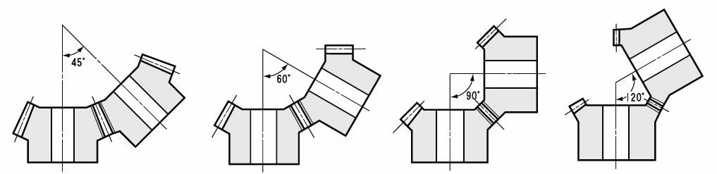
Fig.1.13 Shaft Angles of KHK Stock Gears
From left to right : Shaft Angle 45° / Shaft Angle 60° / Shaft Angle 90° / Shaft Angle 120°
1-4 Nonparallel and Nonintersecting Gears
Gears involving two axis, which are not intersected or parallel, are called Nonparallel and Nonintersecting Axis Gears. They are generally used as worm gear pairs or screw gears. These gears transmit rotational force/power by the relative slippage between gear-tooth surfaces.
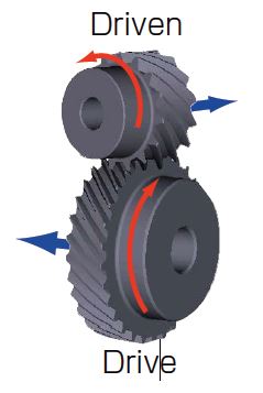
Screw Gear (Crossed Helical Gear)
This is a helical gear with a spiral angle at 45 degrees. A pair of gears, nonparallel and are nonintersecting and have the same helix hands, are called screw gears. They work very quietly, but, can only be used for light loads.
Characteristics / Technical Hints :
– Care should be taken for lubrication. The slippage of the meshed faces transmits rotational force / power. Lack of proper lubrication may cause rapid wear.
– Efficiency is low when compared to parallel axis / intersecting axis gears.
– Used in low power transmission
– There is no limits to the number of teeth of paired gears. (differing from Bevel Gears)
The direction of rotation and thrust force on right-helical (R) / left-helical (L) combinations are shown in the Figure 1.14.
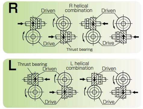
Fig.1.14 Direction of Rotation and Thrust Force
(Important Gear Terminology and Gear Nomenclature in Fig 1.14)
- Thrust bearing
Speed Ratio :
This formula for the speed ratio is the same as it for spur gears.
Speed Ratio
= Number of teeth of Driven Gear / Number of teeth of Drive Gear
(1.6)
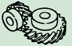
Worm Gear Pair
A Worm Gear pair is a set of gears, where one gear is a worm having screw threads and the other is a meshed worm wheel. Worm gear pairs are often used in power transmission with highreduction or high-torque.
Speed Ratio :
Speed Ratio
= Number of teeth of Worm Wheel / Threads of Worm
(1.7)
The direction of rotation and thrust forces on right-helical (R) / left-helical (L) worm mesh, are shown in Figure 1.15.
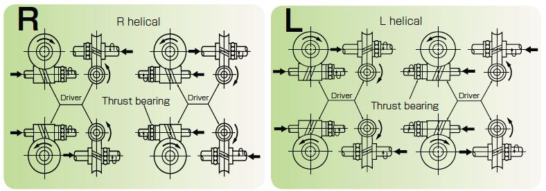
Fig.1.15 Direction of Rotation and Thrust Forces
(Important Gear Terminology and Gear Nomenclature in Fig 1.15)
- Thrust bearing
Characteristics / Technical Hints :
– Large reduction ratio can be obtained by a single-stage train
– Efficiency is low if compared with parallel-axis gears or intersecting-axis gears
– Worm gear pairs must be designed and produced as a pair. Gear-cutting is applied by a selective cutting machine in accordance with the base diameter of the meshing worm.
– As with screw gears, slippage occurs on the tooth surface of gears in mesh. Care should be taken for lubrication. Lack of proper lubrication may cause rapid wear.
Calculation Example :
Threads of the worm z1 = 2 , Number of teeth of the worm wheel z2 = 40
Speed Ratio
= 40 / 2
= 20
Related links :
齿轮的种类及特长
Know about rotational directions and numbers of rotation of gears
Know about gear types and relations between the two shafts
Know about gear transmission torque
Types of Gears
Characteristics of Gears
Gear Types and Terminology
Types and Mechanisms of Gear Reducers