


4. Gear Profile Shift / Usage of profile-shifted gears enables more strength, by adjusting the center distance.
When you use gears, you might find a situation that you need to adjust the center distance to create more strength. In this section, we introduce profile shifting by changing tooth profile, or tooth thickness.
Gears are divided into two types, one is a standard gear, and the other is a profile-shifted gear. Standard gears have a basic tooth profile as shown in Figure 4.1. Profile shifting is applied to create gears with tooth thickness that is different from standard gears. By making the tooth thickness of involute gears thicker or thinner, you can change gear strength and the center distance of paired gears.
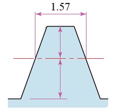
Fig. 4.1 Tooth profile of a rack with Module 1
Addendum : 1.0
Dedendum : 1.25
Number of Teeth and Tooth Profiles
Although the tooth profile of racks is straight, the tooth profile of involute gears differs depending on the number of teeth. Involute tooth profile is curvilinear, but becomes straighter like the tooth profile of a rack, if the number of teeth is increased.
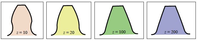
Fig. 4.2 Tooth profiles varied by number of teeth
When the number of teeth is increased, the tooth profile gets thicker at the tooth-root and can generate more strength. As for the tooth profile of a 10-teeth gear, it is gouged at the tooth-root and under-cutting occurs.
Small <— Number of Teeth —> Large
Small <— Tooth Thickness at Root —> Large
Small <— Strength —> Large
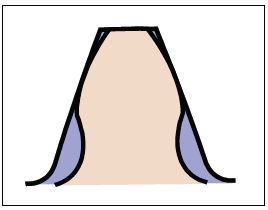
Fig. 4.3 Comparison of Tooth Profiles : z10 × z200
By applying a positive correction and increasing the tip diameter and thickness, 10-teeth gears can also obtain the strength of a 200-teeth gear (z=200).
Profile Shifted Gear
Figure 4.4 shows gear cutting for a positive correction of 10-teeth gear (z =10). The amount of shift or correction made when applying gear cutting is called the extra feed of gear cutter xm (mm).
xm = Extra feed of gear cutter (mm)
x = Profile Shift Coefficient
m = Module (mm)
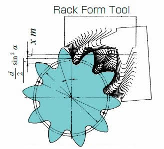
Fig. 4.4 Generation of Positive Shifted Spur Gear
( α = 20° , z = 10 , x = + 0.5 )
(Important Gear Terminology and Gear Nomenclature in Fig 4.4)
- Rack Form Tool
As in Figure 4.5, if profile shifting (Profile Shift coefficient x = +0.5) is applied, the tooth profile is changed and the tooth thickness increases. Outside diameter (Tip diameter) also becomes larger. It is also notable that positive correction is effective to prevent undercut. There are also other reasons for applying profile shifting, stated below.
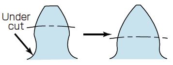
Fig. 4.5 Comparison with Positive Shifted Tooth Profile
(Important Gear Terminology and Gear Nomenclature in Fig 4.5)
- Under cut
Changing the Center Distance
Reference center distance of the standard gear (without shifting) is the half value of the sum of reference diameters. Profile shifted gears allow you to enlarge or reduce the center distance.
Positive correction -> Enlarge the center distance
Negative correction -> Reduce the center distance
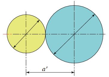
Fig. 4.6 Center Distance of Positive Shifted Gear
Characteristics and technical hints for Profile Shifted Gears
There are limits in profile shifting, for both positive correction and negative correction.
Positive Correction
– Forms a tooth profile that has more bending strength, as the tooth thickness becomes thicker at the root.
– Contact ratio becomes smaller, as the working pressure angle becomes larger by the increase of the center distance.
– Tooth tip might be sharpen, more shifting is applied, the tooth width at the tip gets smaller, and the tooth tip becomes sharpen if it exceeds the limit in shifting.
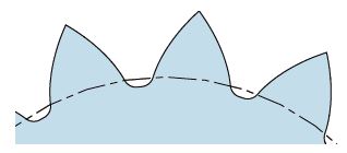
Fig. 4.7 Pointed Tooth-tips
Negative Correction
– Forms a tooth profile that has less bending strength, as the tooth thickness becomes thinner at the root.
– Contact ratio becomes larger, as the working pressure angle becomes smaller by the decrease of the center distance.
– Undercut may occur, more shifting is applied, the tooth width at root gets smaller, undercut occurs if it exceeds the limit in shifting.
Appendix : Profile Shifted Tooth Cutting Method and Profile Shifted Gears
[1] Preventing cutting down of gear teeth
The tooth form of rack cutters for involute gears is a straight line. If the cutter is shifted in the direction of the radius of the gear being cut so that the rack cutter’s standard pitch line and the original pitch line separates, the same involute gear with the same base circle diameter (= zmc cos αc) and the normal pitch (= πmc cos αc) will be created as shown in Figure 2.29.
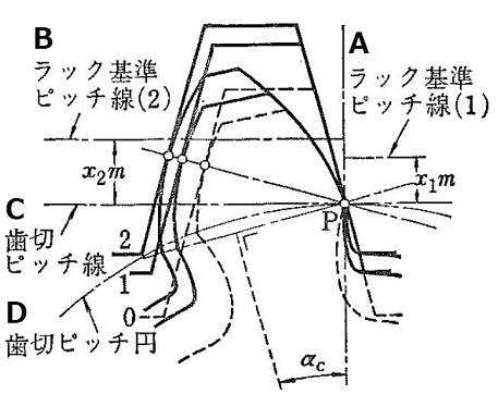
Figure 2.29 Various tooth forms created from the same tool by profile shifting
A and B – Rack standard pitch line
C – Tooth cutting pitch line
D – Tooth cutting pitch circle
Therefore, if one side or both of a pair of gears is cut in this manner, there is no change in angular speed ratio, and they should have the correct meshing. These gears are called profile shifted gears.
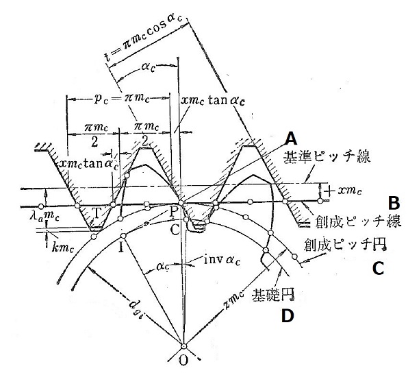
Figure 3.30 The original tooth cutting using rack shaped cutter
A – Standard pitch line
B – Original pitch line
C – Original pitch circle
D – Base circle
As shown in Figure 2.30, assume the amount of shifting of the rack cutter’s standard pitch line from the original pitch line to be xmc (x is called the coefficient of profile shift and x<0 if the shift is toward the gear) and the height of rack’s standard pitch line to the tip of the rack cutter T (the tip of straight line cutter to create involute) as λαmc, then λ in Formula (2.1) becomes λ = λα – x and
z ≥ 2 (λα – x) / sin2 αc (2.4)
This can be rewritten as the following
x ≥ λα [ 1 – ( z / zo )] (2.5)
where
zo = 2 λα / sin2 αc (2.5)’
( z ≥ 2 λ / sin2 αc (2.1) )
The above equations represent the relationship between the number of teeth and profile shifting coefficient for not creating the tooth cut down. When x = 0, z ≥ z0, and z0 leads to no profile shift, or in other words, it indicates the minimum number of teeth which does not cause cut down of standard gears. Therefore, as stated above, for 14.5° full depth tooth (α = 1), z0 = 31.9 ≈ 32, and for 20° full depth tooth, z0 = 17.1 ≈ 17. In actuality, a certain amount of tooth cut down is permitted so that when λα = 1, the following practical cut down limiting profile shifting coefficient is sometimes used.
x = ( z0’ – z)/ z0, z0’ ≈ (5/6) z0 (2.6)
It is normal (as in DIN, etc.) to specify z0 = 26 for αc = 14.5° and z0 = 14 for αc = 20°. Figure 2.31 shows the limit of tooth cut down. Also shown is the limit when the tooth tip becomes a sharp point due to the large amount of profile shift.
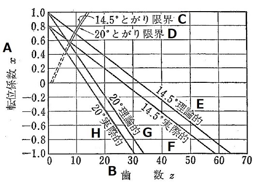
Figure 2.31 Limits of tooth cut down and tooth tip becoming a point
A – Profile shifting coefficient x
B – Number of teeth z
C – Limit where tip becomes pointed for 14.5°
D – Limit where tip becomes pointed for 20°
E – 14.5° theoretical
F – 14.5° practical
G – 20° theoretical
H – 20° practical
Related links :
Profile Shifted Gears
齿轮的变位