


5. Gear Accuracy / High accuracy in a gear denotes a gear that will produce less errors.
A gear must work in transmitting rotation/power from one gear axis to another, efficiently and quietly. To improve gear accuracy is to improve the performance of a gear.
- Gear accuracy can be loosely classified into 3 types
- The datum of gear accuracy is the centerline (gear axis) of a gear
- Higher accuracy gears have less errors
- Precision in involute tooth profile -> Profile Deviation
- Precision in tooth face / tooth trace -> Helix Deviation
- Precision in positioning of teeth / tooth-spaces
- Precision in tooth positioning -> Single Pitch Deviation
- Precision in pitch -> Total Cumulative Pitch Deviation
- Variation of the position of a ball inserted in each tooth space, around the gear -> Runout Error of Gear Teeth
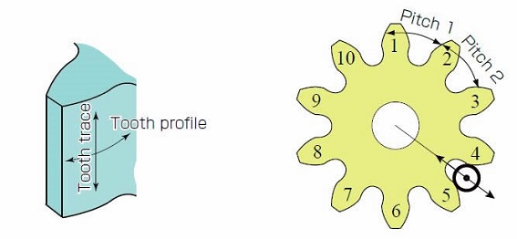
Fig. 5.1 Gear Accuracy
(Important Gear Terminology and Gear Nomenclature in Fig 5.1)
- Tooth trace
- Tooth profile
- Pitch
Profile Deviation (Fα)
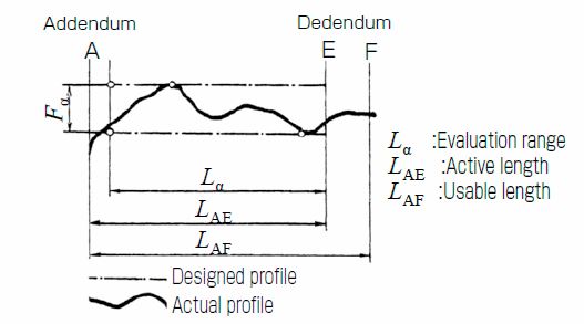
Fig. 5.2 Total Profile Deviation Fα
(Important Gear Terminology and Gear Nomenclature in Fig 5.2)
- Addendum
- Dedendum
- Evaluation range
- Active length
- Usable length
- Designed profile
- Actual profile
Helix Deviation (Fβ)
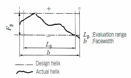
Fig. 5.3 Total helix deviation Fβ
(Important Gear Terminology and Gear Nomenclature in Fig 5.3)
- Evaluation range
- Face width
- Design helix
- Actual helix
Pitch Deviation
The pitch value is measured on a measurement-circle where the center is the gear axis.
(a) Single Pitch Deviation (fpt)
The deviation between actual measurement pitch value and theoretical circular pitch.
(b) Total Cumulative Pitch Deviation (Fp)
Evaluated by measuring the accumulative pitch deviation of the total amount of gear teeth, where the overall amplitude of accumulative pitch error curve is the total cumulative pitch deviation.
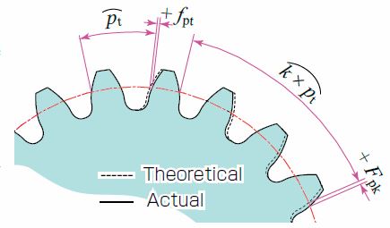
Fig. 5.4 Pitch Deviation
Runout Error of Gear Teeth (Fr)
Runout error is measured by indicating the position of a pin or ball inserted in each tooth space around the gear and taking the largest difference. The values of runout include eccentricity.
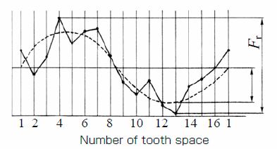
Fig. 5.5 Runout error of a 16-tooth gear
Total Radial Composite Deviation (Fi)
Tooth profile / Pitch / Tooth space are factors to evaluate gear accuracy by measuring a single gear. There is also another method to evaluate gear accuracy, which is the double flank meshing test method; a measurement of a gear meshed with the master gear. This method measures the variation in the center distance when the gear is rotated one revolution, in a tight mesh with a master gear.
Figure 5.6 is the test result for the 30-tooth gear. It shows 30 small mountain-like waves, representing the tooth-to-tooth radial composite deviation. The value of total radial composite deviation would be similar to the sum of runout error and tooth-to-tooth radial composite deviation.
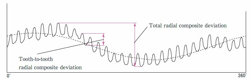
Fig 5.6 Test result of Total Radial Composite Deviation
(Important Gear Terminology and Gear Nomenclature in Fig 5.6)
- Total radial composite deviation
- Tooth-to-tooth radial composite deviation
Related links :
齿轮的精度
Accuracy of Gears – Testing and Inspecting
Accuracy of Gears