

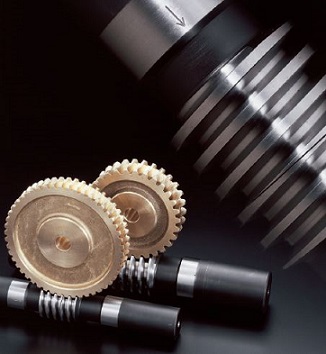
Description of duplex worm gears
The usual method of adjusting the backlash of a worm gear assem-bly is to modify the center distance. Once assembled, such adjust-ment requires a major rework of the gearbox housing. The use of duplex worm gears allows the backlash adjustment to be made by axially shifting the worm. This simplifies greatly the assembly and maintenance operations. Because of the unique characteristics of the product, please take time to study its construction and proper use.
Backlash adjustment mechanism and method of adjustment
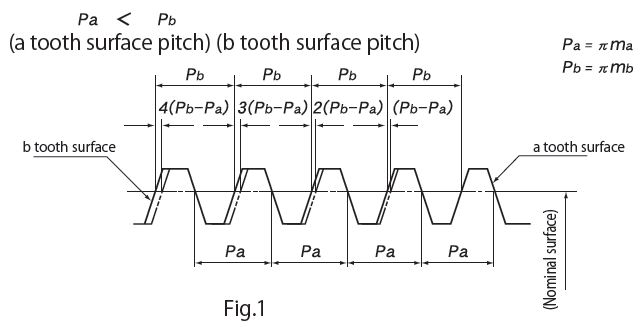
The dual-lead worm is formed to give a difference between the right tooth surface and left tooth surface so that it provides a unique tooth profile in which the tooth thickness varies continuously, corresponding with the lead difference. (Fig.1)
The worm gear is also formed in its right and left tooth surface.
When such a worm and worm gear are set up at a constant assembly distance and the worm is moved in the axial direction, the tooth thickness of the worm in mesh with the worm gear changes making backlash adjustment possible.
[CAUTION] The amount of change in backlash ( △ j mm) in relation to the axial movement of the duplex worm shaft (V mm) can be calculated from the formula below.
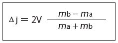
Where
ma = Nominal Axial Module - (0.01 × Nominal Axial Module)
mb = Nominal Axial Module + (0.01 × Nominal Axial Module)
An arrow marking on the outer circumference of the hub of the KHK duplex worm indicates the direction of assembly as well as acts as a guide for the backlash adjustment.
When the worm is held with arrow mark pointing right, the tooth thickness is thinner on the right and thicker on the left. Therefore, moving the worm to the right causes the thicker teeth to come into actual engagement with the worm gear, thereby reducing the backlash. (Fig.2)
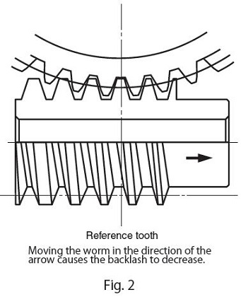
[CAUTION] The KHK duplex worm is designed so that, for all modules, the backlash reduces by 0.02 mm when the worm is shifted 1 mm.
Application Examples
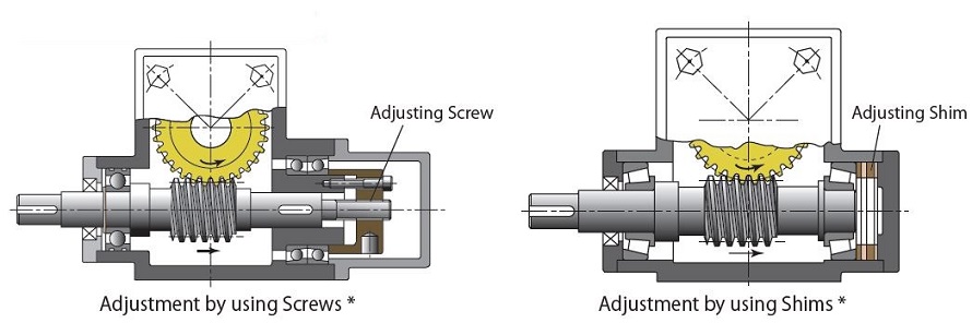
* The illustration above is a design example, not a design for machinery or a device in actual use.
Point of caution during assembly
KHK duplex worm gears differs in module between the right and left tooth surface and, therefore, you must orient the worm and worm wheel properly. Please carefully verify the following two aspects be-fore proceeding with assembly.
1. Verifying the orientation of assembly
An arrow indicating the orientation of assembly is stamped on both the duplex worm and worm wheel. When assembling the worm and worm wheel, check the worm wheel of the arrow mark on the front such that the direction of arrow mark on the worm coincides with that on the worm wheel. Should the assembly be incorrect, the center distance “a” will become larger than the normal distance, resulting in difficulty of assembly and improper gear engagement. (Fig.3)
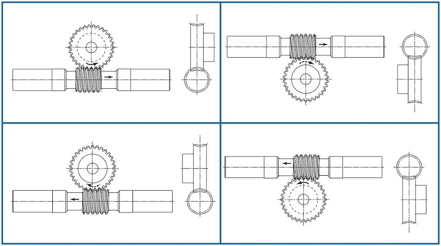
Fig.3 Arrow mark indicates the correct orientation of two gears when assembled. As shown, the two arrows must point in the same direction.
2. Verifying the reference position
A V-groove (60 ゜, 0.3 mm deep line) on tip peripheral of the duplex worm tooth marks the reference tooth. The gear set is designat-ed to have a backlash of nearly zero ( ± 0.045) when the reference tooth is positioned in alignment with the center of rotation of the worm wheel with the center distance set at the value "a". (Fig.4)
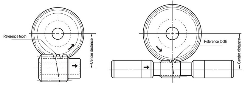
Fig.4
Related links:
How To Use Worm Gears