


For power transmission gears, the tooth form most commonly used today is the involute profile. Involute gears can be manufactured easily, and the gearing has a feature that enables smooth meshing despite the misalignment of center distance to some degree.
3.1 Module Sizes and Standards
Fig. 3.1 shows the tooth profile of a gear rack, which is the standard involute gear profile.
Table 3.1 lists terms, symbols, formulas and definitions related to gear tooth profiles.
The tooth profile shown in Fig 3.1, where the tooth depth is 2.25 times the module, is called a full depth tooth. This type of full depth tooth is most common, but other types with shorter or longer tooth depths are also used in some applications. Although the pressure angle is usually set to 20 degrees, can be 14.5 or 17.5 degrees in specific applications.
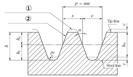
1. Reference tooth profile of a rack standardized for the mating gear
2. Reference tooth profile of a standard rack
Fig. 3.1 Standard basic rack tooth profile
Table.3.1 Symbols related to Gear Tooth Profile
Module
Symbols :
Formula : p/π
Definition : Module is the unit size indicated in millimeter (mm). The value is calculated from dividing the reference pitch by Pi (π).Pitch
Symbols :
Formula : πm
Definition : Reference Pitch is the distance between corresponding points on adjacent teeth. The value is calculated from multiplying Module m by Pi(π).Pressure Angle
Symbols :
Formula : (Degree)
Definition : The angle of a gear tooth leaning against a normal reference line.Addendum
Symbols :
Formula : 1.00m
Definition : The distance between reference line and tooth tip.Dedendum
Symbols :
Formula : 1.25m
Definition : The distance between reference line and tooth root.Tooth Depth
Symbols :
Formula : 2.25m
Definition : The distance between tooth tip and tooth root.Working Depth
Symbols :
Formula : 2.00m
Definition : Depth of tooth meshed with the mating gear.Tip and Root Clearance
Symbols :
Formula : 0.25m
Definition : The distance (clearance) between tooth root and the tooth tip of mating gear.Dedendum Fillet Radius
Symbols :
Formula : 0.38m
Definition : The radius of curvature between tooth surface and the tooth root.
The data in table 3.2 is extracted from JIS B 1701-2: 1999 which defines the tooth profile and dimensions of involute spur gears and helical gears. It is recommended to use the values in the series I and not to use with Module 6.5, if possible.
Table 3.2 Standard values of module Unit: mm
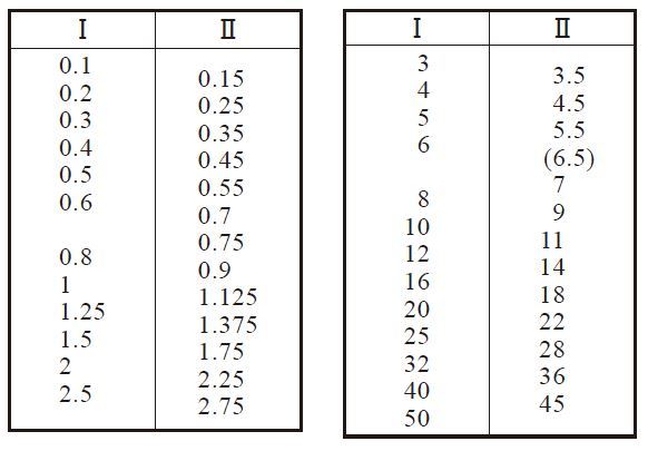
* Extracted from JIS B 1701-2: 1999 Cylindrical Gears for general engineering and for heavy engineering - Part 2 : Modules.
Figure 3.2 shows the comparative size of various rack teeth.
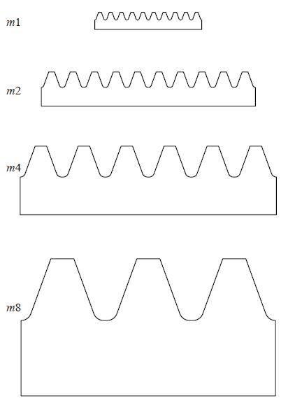
Fig. 3.2 Comparative size of various rack teeth
To indicate tooth size, there are two other units as well as the Module; Circular Pitch (CP) and Diametral Pitch P (D.P). Circular Pitch denotes the reference pitch P. If the reference pitch is set to an integer value, an integral feed in a mechanism is easily obtained.
Diametral Pitch P (D.P.), the unit to denote the size of the gear tooth, is used in the USA, the UK, and other countries. The transformation from Diametral Pitch P (D.P.) to module m is accomplished by the following equation :
m = 25.4 / P (3.1)
Table 3.3 shows the pitch comparisons
Table 3.3 Pitch comparisons
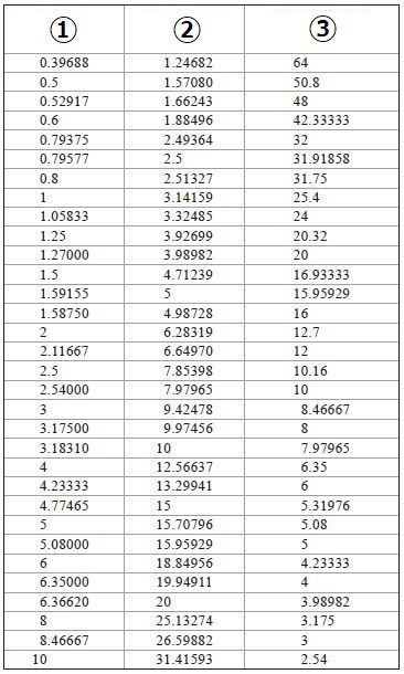
1. Module (m)
2. Circular Pitch (CP)
3. Diametral Pitch (DP)
3.2 The Involute Curve
Figure 3.3 shows an element of involute curve. The definition of involute curve is the curve traced by a point on a straight line which rolls without slipping on the circle. The circle is called the base circle of the involutes.
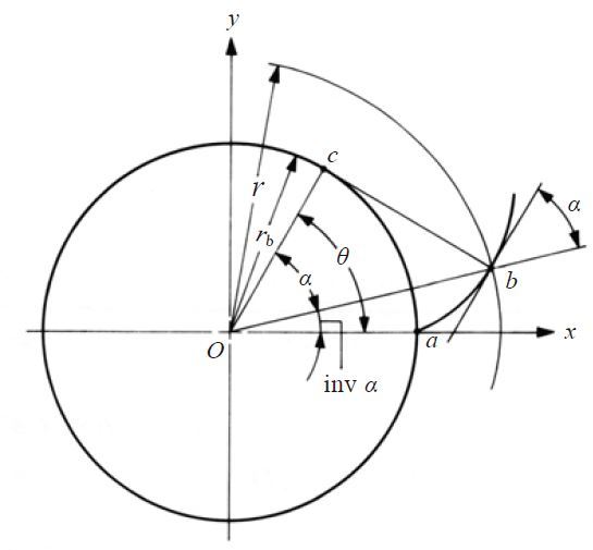
Fig. 3.3 The Involute Curve
In Fig.3.3, invα stands for Involute Angle (Involute α). The units for inv α is radians. θ is called involute rolling angle.
inv α = tan α - α ( rad ) (3.2)
With the center of the base circle O at the origin of a coordinate system, the involute curve can be expressed by values of x and y as follows :
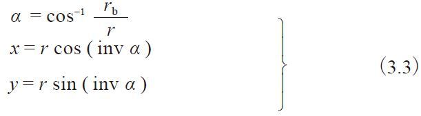
Table 3.4 Calculation Example: The coordinates of an Involute Curve
| Gear Specifications | Set Value | Gear Specifications | Set Value |
| Module | 5 | Reference diameter | 150 |
| Pressure Angle | 20 | Base Diameter | 140.95389 |
| Number of teeth | 30 | Tip diameter | 160 |
| r (Radius) | α (Pressure Angle) | x - coordinate | y - coordinate |
| 70.47695 | 0.00000 | 70.4769 | 0.0000 |
| 72 | 11.80586 | 71.9997 | 0.2136 |
| 74 | 17.75087 | 73.9961 | 0.7628 |
| 76 | 21.97791 | 75.9848 | 1.5192 |
| 78 | 25.37123 | 77.9615 | 2.4494 |
| 80 | 28.24139 | 79.9218 | 3.5365 |
The following method was used to create the above table :
1. Determine Radius ( r )
2. Calculate the coordinate of pressure angle α, x/y using the formulas (3.3)
3.3 Meshing of Involute Gear
Figure 3.4 shows a pair of standard gears meshing together. The contact point of the two involutes, as Figure 3.4 shows, slides along the common tangent of the two base circles as rotation occurs. The common tangent is called the line of contact, or line of action. A pair of gears can only mesh correctly if the pitches and the pressure angle are the same. The requirement that the pressure angles must be identical becomes obvious from the following equation for base pitch pb :
pb = πm cos α (3.4)
Thus, if the pressure angles are different, the base pitches cannot be identical. The contact length ab shown in Figure 3.4 is described as the "Length of the path of contact". The contact ratio can be expressed by the following equation :
Transverse Contact Ratio εα = Length of path of contact ab / Base pitch pb (3.5)
It is good practice to maintain a transverse contact ratio of 1 or greater. Module m and the pressure angle α are the key items in the meshing of gears.
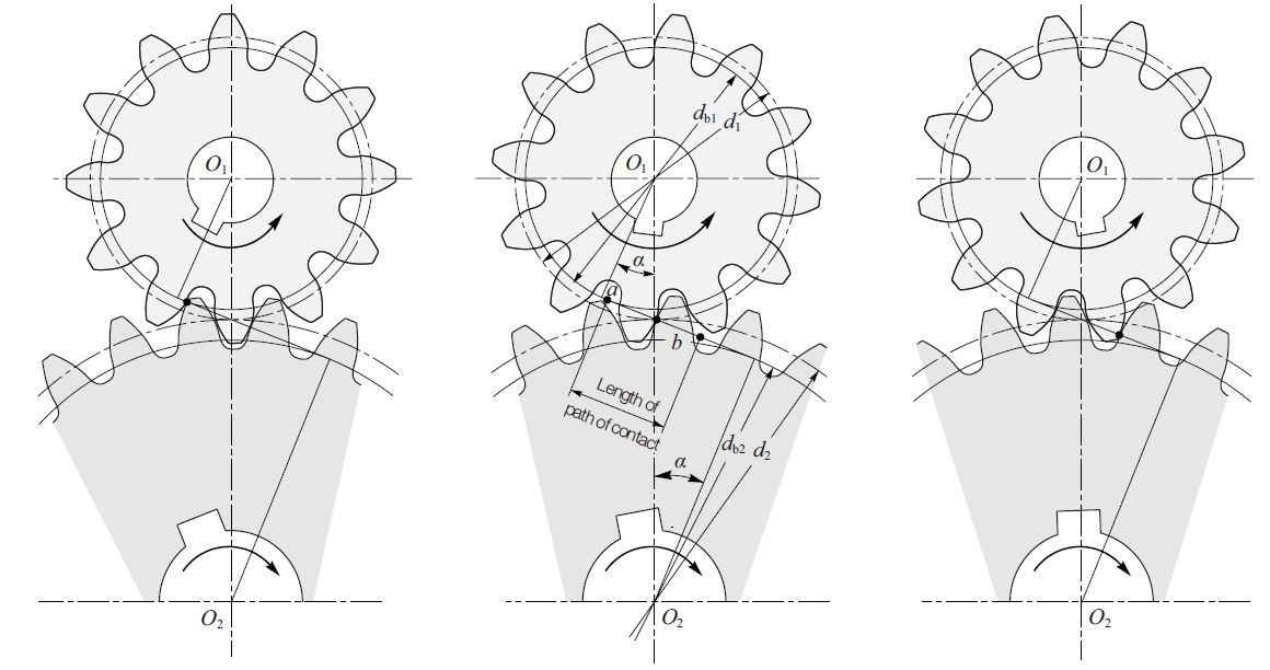
Fig. 3.4 Meshing of Involute Gear
3.4 The Generating of a Spur Gear
Involute gears can be easily generated by rack type cutters. The hob is in effect a rack cutter. Gear generation is also produced with gear type cutters using a shaper or planer machine. Figure 3.5 illustrates how an involute gear tooth profile is generated. It shows how the pitch line of a rack cutter rolling on a pitch circle generates a spur gear. Gear shapers with pinion cutters can also be used to generate involute gears. Gear shapers can not only generate external gears but also generate internal gear teeth.
Fig. 3.5 Generation of a Standard Spur Gear
(α = 20°, z = 10, x = 0)
3.5 Undercutting
When cutting a stock spur pinion like the gear shown in Fig. 3.5, undercutting occurs if you cut deeper than the interfering point. I. Undercutting is a phenomenon that occurs when some part of tooth dedendum is unexpectedly cut by the edge of the generating tool (hc). The condition for no undercutting in a standard spur gear is given by the expression :
Max addendum
and the minimum number of teeth (z) is:
For pressure angle 20 degrees, the minimum number of teeth free of undercutting is 17. However, gears with 16 teeth or less can be usable if their strength and contact ratio pose any ill effect.
3.6 Profile Shifting
As Figure 3.5 shows, a gear with 20 degrees of pressure angle and 10 teeth will have a huge undercut volume. To prevent undercut, a positive correction must be introduced. A positive correction, as in Figure 3.6, can prevent undercut. Undercutting will get worse if a negative correction is applied. See Figure 3.7. The extra feed of gear cutter (xm) in Figures 3.6 and 3.7 is the amount of shift or correction. And x is the profile shift coefficient. The condition to prevent undercut in a spur gear is :
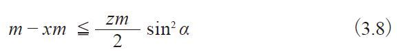
Table 3.5 Calculations of Top Land Thickness (Crest Width )
| No. | Item | Symbols | Symbol | Formula | Example |
|---|---|---|---|---|---|
| 1 | Module | m | mm | Set Value | 2 |
| 2 | Pressure angle | α | Degree | 20 | |
| 3 | Number of Teeth | z | - | 16 | |
| 4 | Profile Shift Coefficient | x | - | 0.3 | |
| 5 | Reference Diameter | d | mm | zm | 32 |
| 6 | Base Diameter | db | dcosα | 30.07016 | |
| 7 | Tip Diameter | da | d+2m(1+x) | 37.2 | |
| 8 | Tip Pressure Angle | αa | Degree | Cos-1 db/da | 36.06616 |
| 9 | Involute α | invα | Radian | tanα-α | 0.014904 |
| 10 | Involute αa | invαa | tanαa-αa | 0.098835 | |
| 11 | Tip Tooth Thickness Half Angle | ψa | π/2z+2xtanα/z+(invα-invαa) | 0.027893 | |
| 12 | Crest Width | sa | mm | ψada | 1.03762 |
The number of teeth without undercut (z) will be:

The profile shift coefficient without undercut (x) is:
Profile shift is not merely used to prevent undercut, it can also be used to adjust the center distance between two gears. If a positive correction is applied, such as to prevent undercut in a pinion, the tooth tip is sharpened.
Table 3.5 presents the calculation of top land thickness (Crest width).
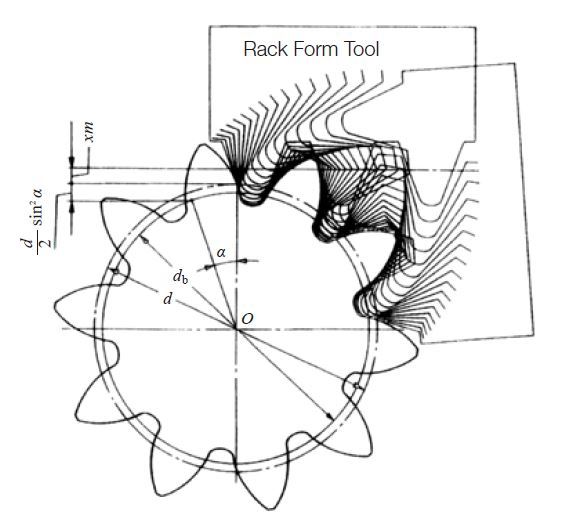
Fig. 3.6 Generation of Positive Shifted Spur Gear
( α = 20°, z = 10, x = +0.5)
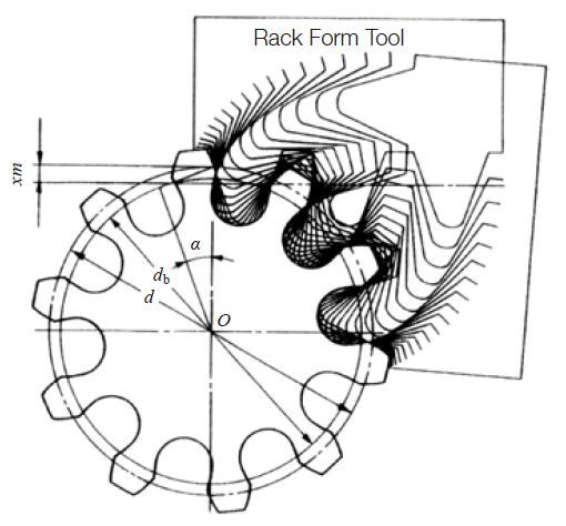
Fig. 3.7 Generation of Negative Shifted Spur Gear
( α = 20°, z = 10, x = -0.5)
Fig. 3.8 Top Land Thickness
3.7 Gear Tooth Modifications
There are many unique technical words related to gearing. Also, there are various unique ways of modifying gears. This section introduces some of most common methods.
(1) Tooth Profile Modification
Tooth Profile Modification generally means adjusting the addendum. Tooth profile adjustment is done by chamfering the tooth surface in order to make the incorrect involute profile on purpose. This adjustment, enables the tooth to vault when it gets the load, so it can avoid interfering with the mating gear. This is effective for reducing noise and longer surface life. However, too much adjustment may create bad tooth contact as it is functions the same as a large tooth profile error.
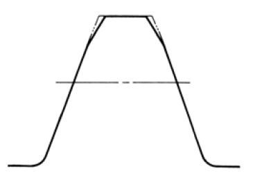
Fig. 3.9 Tooth Profile Modification
(2) Crowning and End Relief
Crowning is the removal of a slight amount of the tooth from the center on out to the reach edge, making the tooth surface slightly convex. This method allows the gear to maintain contact in the central region of the tooth and permits avoidance of edge contact. Crowning should not be larger than necessary as it will reduce the tooth contact area, thus weakening the gears strength. End relief is the chamfering of both ends of tooth surface.
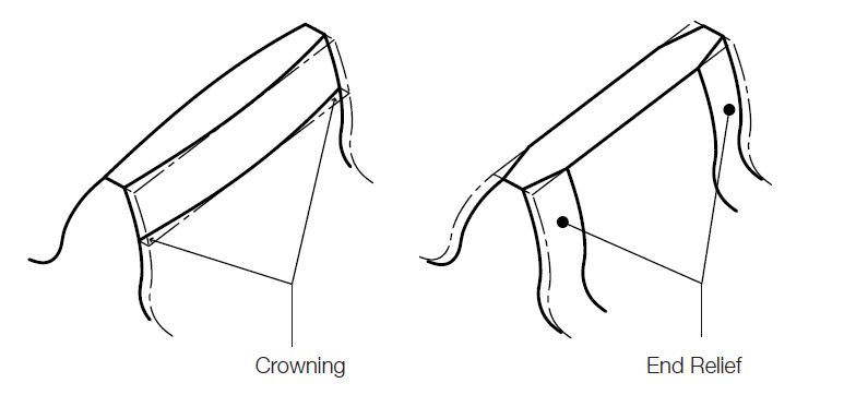
Fig. 3.10 Crowning and End Relief
(3) Topping and Semitopping
In topping, often referred to as top hobbing, the top or tip diameter of the gear is cut simultaneously with the generation of the teeth. Fig. 3.5, 3.6 and 3.7 indicate topping and generating of the gear by rack type cutters. An advantage is that there will be no burrs on the tooth top. Also, the tip diameter is highly concentric with the pitch circle.
Semitopping is the chamfering of the tooth's top corner, which is accomplished simultaneously with tooth generation. Fig.3.11 shows a semitopping cutter and the resultant generated semitopped gear. Such a tooth end prevents corner damage and has no burrs.
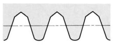
(1) Teeth Form of Semitopping Cutter
(2) Semitopped Tooth Form
Fig. 3.11 Semitopping Cutter and the Gear Profile (1) and (2)
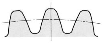
The magnitude of semitopping should not go beyond a proper limit as otherwise it would significantly shorten addendum and contact ratio. Fig. 3.12 shows a recommended magnitude of semitopping.
Topping and semitopping are independent modifications but, if desired, can be applied simultaneously.
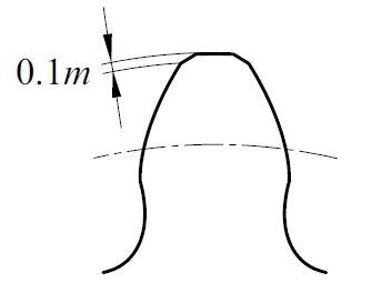
Fig. 3.12 Magnitude of Semitopping
Appendix - Tooth form modification
This article is reproduced with the permission.
Masao Kubota, Haguruma Nyumon, Tokyo : Ohmsha, Ltd., 1963.
It is assumed that it is ideal to produce gears with no defects in tooth forms. Not only is it impossible to avoid some errors, but even if the gears themselves are correct, the assembly process may introduce errors in parallelism of two shafts or eccentricity when mounting gears on the shafts. Even when the assembly is correctly done, because the gear material has elasticity, load on the gear may introduce deflection. Also, at the starting and ending points of mesh engagement and at the instant when simultaneously engaging group of gears changes, it is impossible to avoid the rapid changes in the loading on each tooth. For these reasons, the ideal meshing is not always assured. In order to avoid these realistic deficiencies, it became a common practice to purposely deviate from the geometrically correct tooth forms. This is called tooth form modification.
There are two types of tooth form modifications, modification of perpendicular cross section of tooth and modification of tooth line (crowning).
The actual gears produced may contain pressure angle errors, normal pitch errors and/or bowing of tooth from the load resulting in an elastic approach of contact portion to cause the gauging of the root of the driving gear by the tip of the driven gear. This latter action will cause the driven gear to speed up and produce vibration and noise and likely scrape off any lubricant. In order to avoid this problem, it is better to gradually thin the driven gear’s tip (tip relief) or the driving gear’s root (dedendum modification). If the amount of thinning is appropriate, it can be made so that the loading on the driven gear due to elasticity is gradual. Similarly, by thinning the driving gear’s tooth tip or the driven gear’s root, the departure of the load on the driving gear can be made gradual, avoiding the dangers of one tooth tip of driving gear being subjected to the entire load. BSS (British Standard) specifies the amount of tooth tip thinning as shown in Figure 2.52.
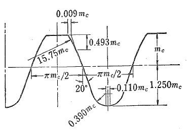
[Figure 2.52 BSS 436 (1940) A2, B Class Standard Spur Gear Rack]
Next, when the teeth are not perfectly parallel, or there is an error in the parallelism of the two shafts in assembling the unit, or when the parallelism is compromised due to the load, they may cause the ends of the face width to hit the mating tooth producing partial contact which leads to early gear failure. As shown in Figure 2.53, if the tooth along the length of its face is thinned toward the edge (approximately 0.001”) (or if the middle of the face width is slightly inflated), then even when there is some error in parallelism, the gear maintains contact near the center of the face width. This is called crowning and if the amount is proper, it increases the gear’s life tremendously. Crowning is used extensively in automotive gears.
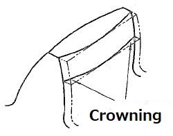
[Figure 2.53 Crowning]
Crowning is usually applied during grinding or shaving operations. It is also sometimes used while hobbing by varying the amount of profile shifting along the tooth width (maximum shifting at the middle of the face width).
It is most desirable when modification of the tooth form perpendicular to the tooth is used with crowning.
Related links :
齿轮的齿形
Know about parameters that determine gear shapes
Pitch point
Gear Tooth Profile
Involute Tooth Profile
Calculation of Gear Dimensions