


Types and Mechanisms of Gear Reducers
This article is reproduced with the permission.
Japan Institute of Plant Maintenance, Shinpan Gensokuki No Hon, Tokyo : JMA Consultants Inc. 2008.
The copyrighted work used here was written in Japanese and was translated solely by KHK Co., Ltd.
A gear speed reducer is a representative example of speed changers, and presently used units can be categorized by the type of gears, shaft positions and arrangement of gears into (1) gear reducer with parallel axes, (2) gear reducer with orthogonal axes, (3) gear reducer with perpendicular non-intersecting axes, and (4) gear reducer with coaxial axes.
Types and mechanisms of gear reducers with parallel axes
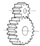
The gear reducers with parallel axes use spur gears, helical gears, or herringbone gears. Their input and output shafts are parallel. As for reduction ratios, 1/1 – 1/7 for one-stage shafts, 1/10 – 1/30 for two-stage shafts, and 1/5 – 1/200 for more than three-stage shafts are commercially available. The general characteristics of gear reducers with parallel axes are as follows :
- For high precision gears, the transmission efficiency is very high. (98 to 95% for one-stage gear reducer)
- When properly lubricated, it can be used for a long time.
- Can be produced relatively cheaply as standardized gears are used.
- Gear reducers with spur gears are used for increasing speed.
The sizes of gear reducers with spur gears are is usually large. Compared to worm gear reducers with the same speed ratio, their outer shapes are large, and the number of parts increases leading to constructional disadvantages. Therefore, it is used for machines with high rotation on the load side, or which need higher output rotation than the prime movers (for increasing speed). The gear types are shown in Table 2.1.
The gear reducers with parallel axes usually use helical gears. They are used in steel facilities, ships, cranes, elevators, and conveyors. As for automation machines, these gear reducers are also known for geared motors which are gear reducers with directly connected motors.
Table 2.1 Characteristics of gear reducers with parallel axes
|
Spur gears : |
Helical gears : |
|
Herringbone gears : |
Types and mechanisms of gear reducers with orthogonal axes
Gear reducers with orthogonal axes are also known as bevel gear reducers, whose input and output shafts are perpendicular. Among the gears used are straight bevel gears, helical bevel gears, spiral bevel gears, Zerol bevel gears, face gears, and crown gears. Gear reducers with orthogonal axes are commonly used as power branching devices on site.
The precision of gear reducers with orthogonal axes are less than gear reducers with parallel axes. Especially, the pinion which is supported only on one side is easy to deflect, leading to a somewhat lower transmission efficiency (98%) due to resulting bad teeth contact. Straight bevel gear reducers are suitable for slow rotation under 1000rpm, and standardized reduction ratios are 1:1 and 1:2.
In addition, the meshing ratio of the spiral bevel gear reducer is large and suitable for high load and high-speed rotation compared to straight bevel gear reducers. Generally, reduction ratio is limited to 1:6 for one stage. Table 2.2 shows the gears for bevel gear reducers.
Types and mechanisms of gear reducers with skew axes
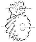
Gear reducers whose input and output axes are offset and orthogonal to each other generally use hypoid gears or worm gears. Especially, worm gears have been used to reduce speed for a long time, and are still used frequently at present. The characteristics of gears used in them are shown in Table 2.3. The distinctive features of these reducers are as follows :
- High reduction ratio in a single stage
The reduction range is between 1:5 and 1:100. It is possible to obtain the reduction ratio of 1:10,000 if two worm gear reducers are combined. - Less noise and vibration
Worm gears generate less noise and vibration as mainly sliding contact occurs. Taking advantage of this characteristic, worm gear reducers have been used for driving sources. However, because of poor transmission efficiency, they have been replaced by gear reducers with orthogonal axes such as using hypoid gears or with parallel axes as discussed later. - Input and output axes are at right angle
There are fewer parts even when integrated into gear boxes and their sizes are small, so that installing areas are saved. - Self-locking property
When the reduction ratio is high, it may be unable to turn the input axis (worm) by using the output axis (worm wheel). (This is called self-locking). In actuality, absolute self-locking is difficult. On the other hand, this characteristic is more effective in case of cam mechanisms where positive and negative direction loads are applied while rotating in one way. - Low transmission efficiency
Friction losses of worm gear drives are large because they use sliding contacts. Therefore, transmission efficiency is low and varies widely depending on the lead angle. (When the lead angle is 5 to 40°, transmission efficiency is 60 to 95%.) Rapid decline of the transmission efficiency when lead angle approaches 15° is their disadvantage. (See Figure 2.1). - Rapid increase in temperature
Worm gears have sliding along tooth trace, aside from sliding along tooth profile. As this slide along tooth trace is very large, if the tooth contact along tooth trace is short, a high surface pressure is produced and the lubricating oil film may be broken. When the temperature at meshing point is high and mineral oil is used, 90°C is considered the limit of the allowable temperature on the outside casing.
Table 2.2 Characteristics of gear reducer with orthogonal axes
| Straight bevel gears | Gears with straight tooth trace is cut on a cone shaped surface. Used when two shafts are intersecting each other. |
| Helical bevel gears | Teeth of helical bevel gears are slanted. Stronger than straight bevel gears. |
| Spiral bevel gears | Tooth trace is curved and tooth contact area is large. Higher strength and lower noise. Rather difficult to manufacture and the axial force is large. Used in a variety of applications. |
| Zerol bevel gears | Spiral bevel gears with zero twisting angle. Axial forces are smaller than those of spiral bevel gears and are similar to those of straight bevel gears. |
| Face gears | Bevel gears cut on circular disks and mesh with spur gears to transmit force. Two axes intersect in some cases. Mainly used for light loads and for simple motion transmission. |
| Crown gears | Bevel gears with flat pitch surface, and equivalent to racks of spur gears. |
Table 2.3 Characteristics of gear reducer with skew axes
| Hypoid gears | A type of bevel gears where two shafts do not intersect, therefore not called bevel gears. Less noise, but difficult to manufacture. Large sliding occurs at the meshing surfaces. |
| Cylindrical worm gears | Reduction ratio is large, but small in size. It is possible to self-lock using the force from the output side. Large sliding occurs at the meshing surfaces. |
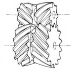
| Hourglass worm gears | Compared to cylindrical worm gears, they have a larger number of meshing teeth which gives them a higher load carrying capacity relative to their sizes. Difficult to manufacture. Tooth contact changes when the worms are moved axially. |
Figure 2.1 worm gear’s transmission efficiency
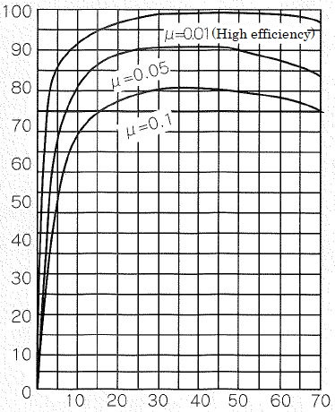
Vertical axis : Transmission efficiency (%)
Horizontal axis : Lead angle (r)
Types and mechanisms of gear reducers with coaxial axes
The coaxial type is also known as the planetary gear type, which is grouped into (1) simple planetary gears, (2) differential planetary gears, (3) eccentric planetary gears, and (4) elastic planetary gears.
The gear reducers with parallel axes or orthogonal axes previously discussed all have gears rotating around fixed axes.
As shown in Figure 2.2, planetary gear reducers are made up of the gear which rotates around the fixed axis (called the sun gear) and the meshed gears which rotate around the sun gear (called the planetary gears).
The Input and output gears can be concentrically installed in the planetary gear reducers to obtain high torque and efficiency, but it is said that it is necessary to transmit power equally to three planetary gears to maximize their ability.
Figure 2.3 shows a type of simple planetary gear reducer. In this compact gear reducer, three to five planetary gears mesh with the internal gear and transmit power from the input sun gear into multiple branches.
If load is uniformly distributed as in the ideal picture, a force of one gear times the number of planetary gears can be transmitted compared to a normal gear drive with one small and one large gear. Distributing forces as evenly as possible is the challenge for designers, and various mechanisms for equidistribution have been developed and put into practical use.
Figure 2.4 shows the structure of TRIRED reducer. One small gear is floated and supported at the center of the three large gears to balance the meshing reaction forces, so that the force branches into three directions.
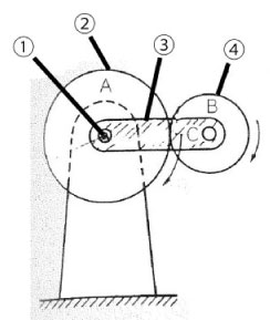
Figure 2.2 Basic structure of planetary gear
1. Fixed axis / 2. Sun gear / 3. Arm (rotation support frame) / 4. Planetary gear
Figure 2.3 Structure example of simple planetary gear reducer
1. Slow axis / 2. Slow axis cover / 3. Case / 4. Internal gear / 5. Planetary gear bearing / 6. Planetary gear / 7. Joint cover / 8. Sun gear / 9. High speed side cover / 10. High speed axis
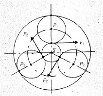
Figure 2.3 Structure example of simple planetary gear reducer (Equidistribution of load)
Figure 2.4 Structure of TRIRED reducer
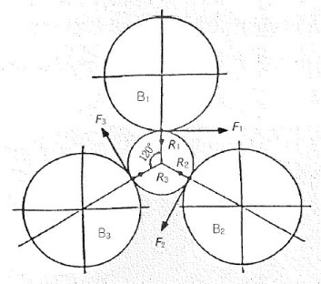
Figure 2.4 Structure of TRIRED reducer (Equidistribution of load)
(1) Structure of the Cyclo speed reducer
Only one or two teeth of normal external gears transmit force at any moment. The next pair of teeth should start meshing before the previous pair completes its meshing to rotate the gear smoothly. The force transmission capacity can be increased by having more teeth meshing simultaneously. For the same motion transmission, this unit is more compact than others. The Cyclo speed reducer is an example of one such type.
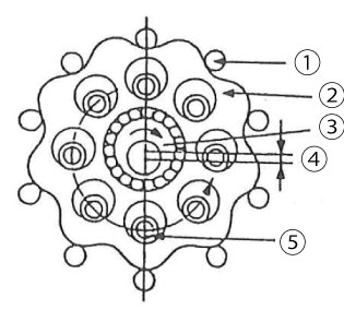
Figure 2.5 Structure of cyclo speed reducer (difference of the number of teeth: 1)
1. Outer pin / 2. Curved plate / 3. Eccentric body / 4. e (eccentric amount) / 5. Inner pin (with inner roller)
As shown in Figure 2.5, this speed reducer is an eccentric differential planetary gear reducer where the fixed internal sun gear with circular arc tooth profile (outer pin) is combined with the planetary gear with trochoidal smooth curved tooth profile (curved plate) with the difference of the numbers of teeth being 1.
The Cyclo speed reducer has a large number of teeth which mesh simultaneously, and resists overload and shock load well for its compact size.
(2) Principle of Cycle speed reducer
Figure 2.6 shows the mechanism of an internal contact type planetary gear. Suppose that the number of teeth of afixed internal sun gear is S, and the number of teeth of a planetary gear is P. The relation of angular speed ω1 and ω2 is expressed in the following formula according to planetary gear theory :
ω2 / ω1 = 1 - S/P = -(S-P)/P
Suppose that S - P=1 (difference of the number of teeth: 1),
ω2 / ω1 = -1/P
For example, in Figure 2.6, assume that number of the teeth of the fixed internal sun gear is S=51, and the number of teeth of planetary gear is P=50. Then theoretically, it is possible to obtain a very large speed reduction of 1/50 using two spur gears.
However, since the general involute tooth form produces tooth tip interference, it is not possible to effectively utilize this mechanism with one tooth difference. The solution to this problem is the one tooth difference planetary gear mechanism shown in Figure 2.7. This internal contact type planetary gear utilizes a circular arc tooth form internal gear and smooth trochoid type curve planet gears resulting in no tooth tip interference and large numbers of teeth in simultaneous mesh.
Next, Figure 2.8 shows an equal velocity internal gear mechanism.
In this mechanism, the center of the planetary gear (curved plate) rotates at high speed (ω1) around the input shaft while its body revolves at low speed (ω2). This structure which extracts the slow speed rotation by combining of circular arc tooth forms, as shown in Figure 2.8, is the equal velocity internal gear mechanism. Ultimately, the rotation of the planetary gear (curved plate) can be taken out to the output axis through inner pins. Since the inner pins are equally positioned around the concentric circle of the crank axis (input shaft) with center Os, they can be attached directly to the output shaft, making the input shaft (high speed axis) and the output shaft (high speed axis) concentric.
The Cyclo speed reducer cleverly combines these two mechanisms and uses rollers on the circular arc tooth profile as shown in Figure 2.9.

Figure 2.6 Principle of internal contact type planetary gear
1. Crank (K) / 2. Revolving input axis / 3. Rotating planetary gear (crank) / 4. Planetary gear (P) / 5. Fixed internal sun gear (S)
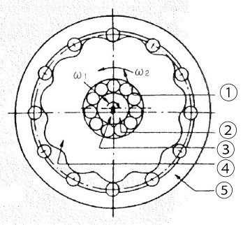
Figure 2.7 Mechanism of one tooth difference internal contact type planetary gear
1. Rotating angular speed of planetary gear / 2. Revolving angular speed of crank / 3. Crank Shaft / 4. Planetary gear (P) / 5. Fixed internal sun gear (S)
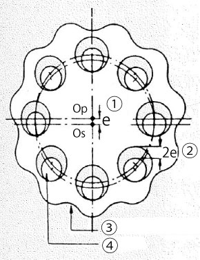
Figure 2.8 Equal velocity internal gear mechanism
1. e (Amount of eccentricity) / 2. 2e (Twice the eccentric amount) / 3. Planetary gear (curved plate) / 4. Inner pin
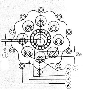
Figure 2.9 Cyclo speed reducer mechanism
1. e (Amount of eccentricity) / 2. 2e (Twice the eccentric amount / 3. Inner pin (with inner roller) / 4. Eccentric body / 5. Curved plate / 6. Outer pin (with outer roller)
(3) Characteristics of the Cyclo speed reducer
- Easy to connect motor directly as input and output axes are concentric.
- Small and light
More parts are used compared to the worm gear type, but the size is compact - Strong against overload and shock load
In general, for involute gears the number of teeth simultaneously in mesh is one or two. On the other hand, the number of teeth of the Cyclo speed reducer meshing simultaneously is theoretically about half of the number of teeth of the curved plate (planetary gear). It is believed the actual value approaches this theoretical amount. As a result, the structure of the Cyclo speed reducer is very strong against shock and overload for its size - Better transmission efficiency than worm gear reducers
Because of its structure, meshing of tooth profiles makes rolling contact so that it produces a transmission efficiency of about 98% for one stage, and even for three stages it can achieve about 94% - Large reduction ratio
As for speed ratios, up to 1:119 for one stage and up to 1:7579 for two stages are commercially available. By using three to six stages, astounding reduction ratio of 1/tens of billions can be obtained
(4) Calculation example of planetary gear
Planetary gear has a pair of meshing gears where both gears rotate while one gear revolves around the axis of the other gear.
An external gear mounted on the fixed axis (center axis) is the sun gear (gear rotates around the fixed axis) and the meshed gear whose axis rotates around the sun gear is the planetary gear.
Consider the case of the planetary gear device shown in Figure 2.10 where planetary gear B (number of teeth= Zb) revolves (number of rotation = nc) around fixed sun gear A (number of teeth = Za) while rotating on its own center (number of rotation = nb).
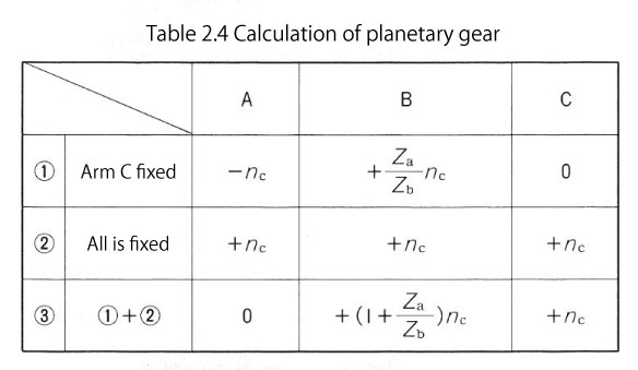
- When arm C is fixed and sun gear A and planetary gear B are in mesh, let sun gear A rotate counterclockwise (-), then the rotations of sun gear A, planetary gear B, and arm C are :
Sun gear A = (-)nc
Planetary gear B = (+) Za/Zb x nc
Arm C = 0
(See Figure 2.11) - When sun gear A, planetary gear B and arm C are each fixed, let sun gear A rotate clockwise (+), then the rotations of sun gear A, planetary gear B, and arm C are :
Sun gear A = (+)nc
Planetary gear B = (+)nc
Arm C = (+)nc
(See Figure 2.12)
Therefore, the number of rotations of a planetary gear device where rotating planetary gear B revolves around fixed sun gear A while rotating on its own axis is the sum of the number of rotations in 1. and 2. (Table 2.4)
As a result, A=0 if the sun gear is fixed and as arm C rotates, the number of rotations of planetary gear B is nb = (1+ Za/Zb) nc.
Let us give some conditions to this expression. In Figure 2.10, how many times does planetary gear B rotate when arm C (rotation support frame) rotates to the right once ? Suppose the number of teeth Za of sun gear A is 80, while the number of teeth Zb of planetary gear B is 40.
The number of rotation nb of planetary gear B is :
nb
= (1+Za/Zb)nc
= (1+80/40)X1 = 3
Therefore, it rotates to the right three times.
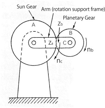
Figure 2.10 Planetary gear device
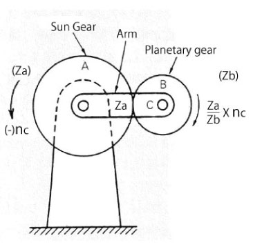
Figure 2.11 Arm C is fixed and A rotates clockwise
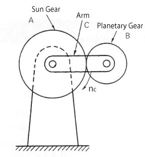
Figure 2.12 All is fixed and A rotates clockwise
Related links :
Know about gear types and relations between the two shafts